44 EMC VNX8000 Hardware Information Guide
System component description
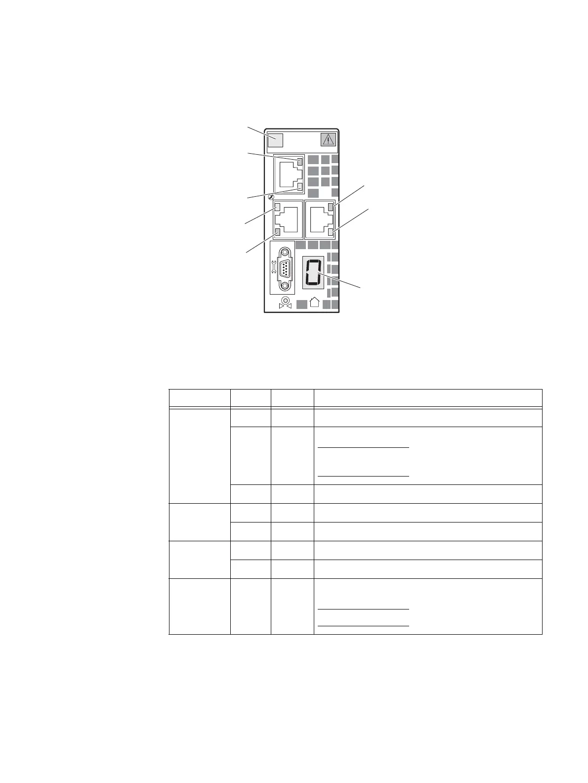
Data Mover management module LEDs
Figure 31 shows the LEDs and Table 18 on page 44 describes them.
Figure 31 Data Mover management module LEDs
Data Mover management module serial console (DB-9) socket connector
The back of the File/Unified VNX8000 platform Data Mover management module includes
a standard serial console Electronics Industries Association (EIA) RS-232 interface (DB-9)
socket connector (labeled with a wrench tool icon on the left). Notice the orientation of
the pins (Figure 32 on page 45).
2
0
1
#
Port 2 (Link LED)
Port 0 (Link LED)
Numeric display
(blade enclosure ID)
Port 1 (Activity LED)
Power/Fault LED
Port 0 (Activity LED)
Port 2 (Activity LED)
Port 1 (Link LED)
CNS-001671
Table 18 Data Mover management module LEDs
LED Color State Description
Power/Fault Green On Data Mover management module is powered up.
Amber On Data Mover management module has faulted.
Note: LED is always illuminated at powerup, until it is
initialized.
—OffData Mover management module is powered down.
Link (each
port has one)
Green On Network connection
— Off No network connection
Activity (each
port has one)
Amber Blinking Transmit/receive activity
— Off No network activity
Numeric
(7-segment)
display for
enclosure ID
— On Displays the enclosure ID assigned to the Data Mover
enclosure.
Note: Each enclosure is assigned a number at installation.

 Loading...


