Disk-array enclosures
EMC VNX8000 Hardware Information Guide 83
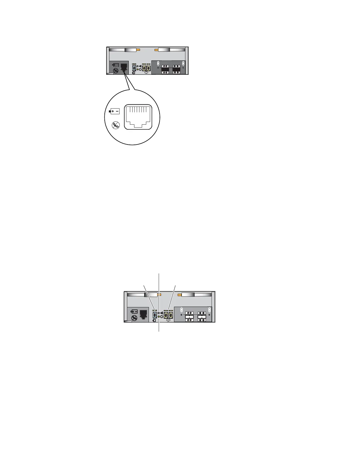
Figure 64 LCC RJ-12 port
The cable connecting the LCC to the SPS is an RJ-12 to RJ-12. It has an RJ-12 adapter (LCC
side) on one end and a RJ-12 (SPS side) adapter on the other end (Figure 17 on page 31).
LCC enclosure ID (enclosure address) and bus ID
On the rear of the LCC (A and B), an LCC enclosure ID indicator is provided. This ID
indicator is a seven-segment LED display for displaying decimal numbers. The LCC
enclosure ID appears on both LCCs (A and B) which is the same ID number. The enclosure
ID is set at installation (Figure 65).
Each LCC includes a bus (loop) identification indicator. This indicator includes two
seven-segment LED displays for displaying decimal numbers. The SP initializes the bus ID
when the operating system is loaded (Figure 65).
Figure 65 Example of an LCC B enclosure ID and bus ID
VNX-000106
6 Gb
SAS
X4
#
X4
6 Gb
SAS
X4
#
X4
Bus (loop) ID
LCC enclosure ID
VNX-000277
LCC power fault LED
LCC power on LED

 Loading...


