Disk-array enclosures
EMC VNX8000 Hardware Information Guide 87
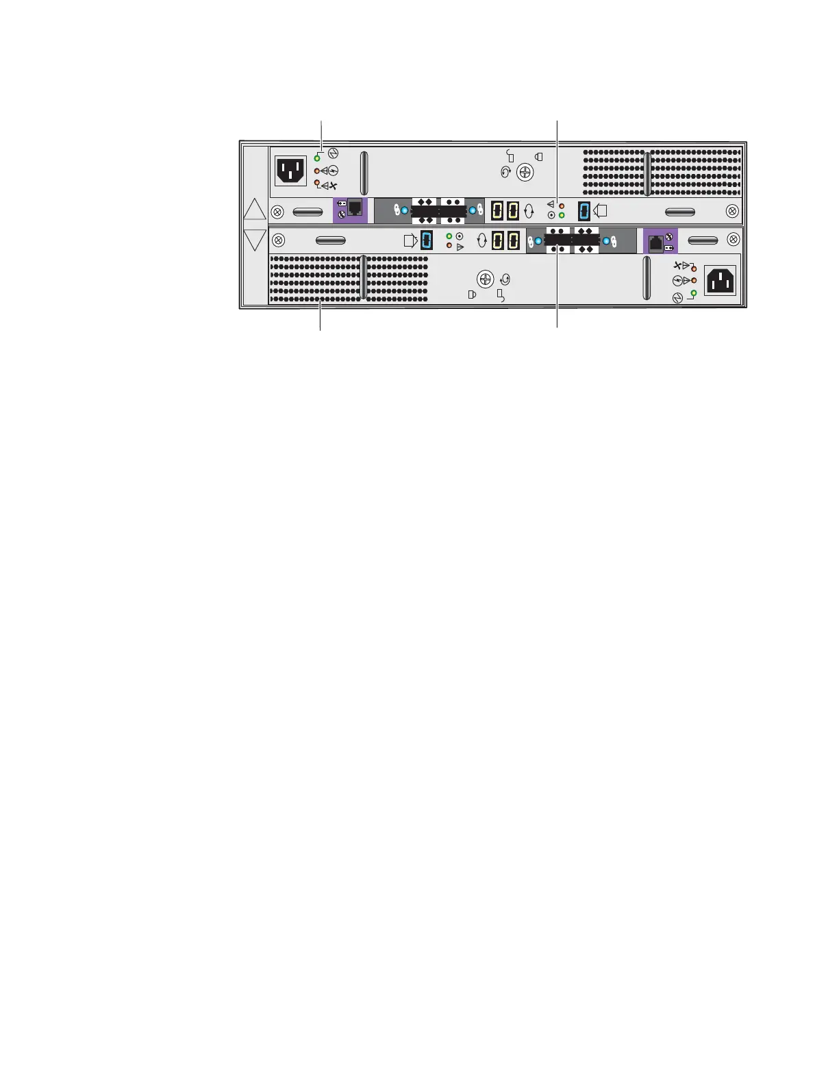
Figure 68 Example of a 3U, 15 (2.5- or 3.5-inch) disk drive DAE with two LCCs and two power
supply/cooling modules (rear view)
3U, 15 (2.5- or 3.5-inch) DAE LEDs and connectors
Figure 69 on page 88 shows the location of the 3U, 15 (2.5- or 3.5-inch) DAE LEDs,
connectors, and the latch handles:
◆ AC power supply (A and B) recessed power in (plug)
◆ AC power supply (A and B) LEDs (power and fault)
◆ AC power supply (A and B) latch handle
◆ LCC (A and B) mini-SAS connectors (input and output)
◆ LCC (A and B) mini-SAS link LEDs
◆ LCC (A and B) bus ID
◆ LCC (A and B) LEDs (power and fault)
◆ DAE enclosure ID
◆ LCC (A and B) management (RJ-12) connector (not used in VNX7600)
◆ LCC (A and B) latch handle
A
B
X4
6Gb SAS
X4
6Gb SAS
LCC B
LCC A
Power supply B
Power supply A

 Loading...


