88 EMC VNX8000 Hardware Information Guide
Disk-array enclosures
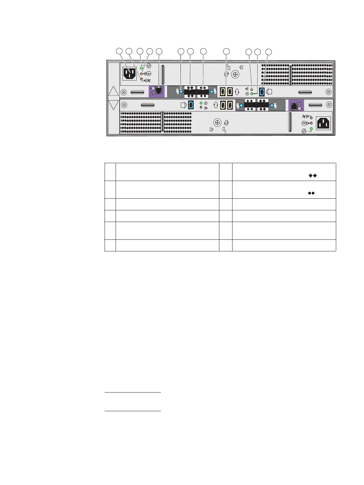
Figure 69 Example of a 3U, 15 (3.5-inch) disk drive DAE with two LCCs and two power
supply/cooling modules (rear view)
LCC
The LCC supports and controls one 6-Gb/s mini-SAS bus and monitors the DAE. A blue
link/activity LED indicates a DAE operating at 6 Gb/s.
The LCCs in a DAE connects to the SPE and other DAEs with 6-Gb/s cables. The cables
connect the LCCs in a system in a daisy-chain (loop) topology.
Internally, each DAE LCC uses protocols to emulate a loop; it connects to the drives in its
enclosure in a point-to-point fashion through a switch. The LCC independently receives
and electrically terminates incoming signals. For traffic from the system’s storage
processors, the LCC switch passes the signal from the input port to the drive being
accessed; the switch then forwards the drive output signal to the port.
Note: If the target drive is not in the LCC’s enclosure, the switch passes the input signal
directly to the output port.
Each LCC independently monitors the environmental status of the entire enclosure, using
a microcomputer-controlled monitor program. The monitor communicates the status to
the storage processor, which polls disk enclosure status. LCC firmware also controls the
SAS PHYs and the disk-module status LEDs.
1 LCC B AC power supply power in (recessed
plug)
7 LCC B SAS connector (output); labeled
with a double diamond symbol
.
2 LCC B power supply fan fault LED (on,
amber)
8 LCC B SAS connector (input); labeled with
a double circle (or dot) symbol
.
3 LLC B power supply LED (on, green) 9 LCC B bus ID
4 LCC B power supply fault LED (on, amber) 10 LCC B bus LED (fault, amber)
5 LCC B management (RJ-12) connector to
SPS
11 LCC B bus LED (on, green)
6 LCC B SAS connector link LED 12 DAE enclosure ID
1
1. The DAE enclosure ID is sometimes referred to as the enclosure address (EA).
A
B
X4
6Gb SAS
X4
6Gb SAS
LCC B
LCC A
VNX-000100
2
4
1
567 9
10 11 12
8
3

 Loading...


