6. (optional) Connect SP A SAS Port 0 to DAE 2 LCC A. See cable 3 in Figure 23 on page
31.
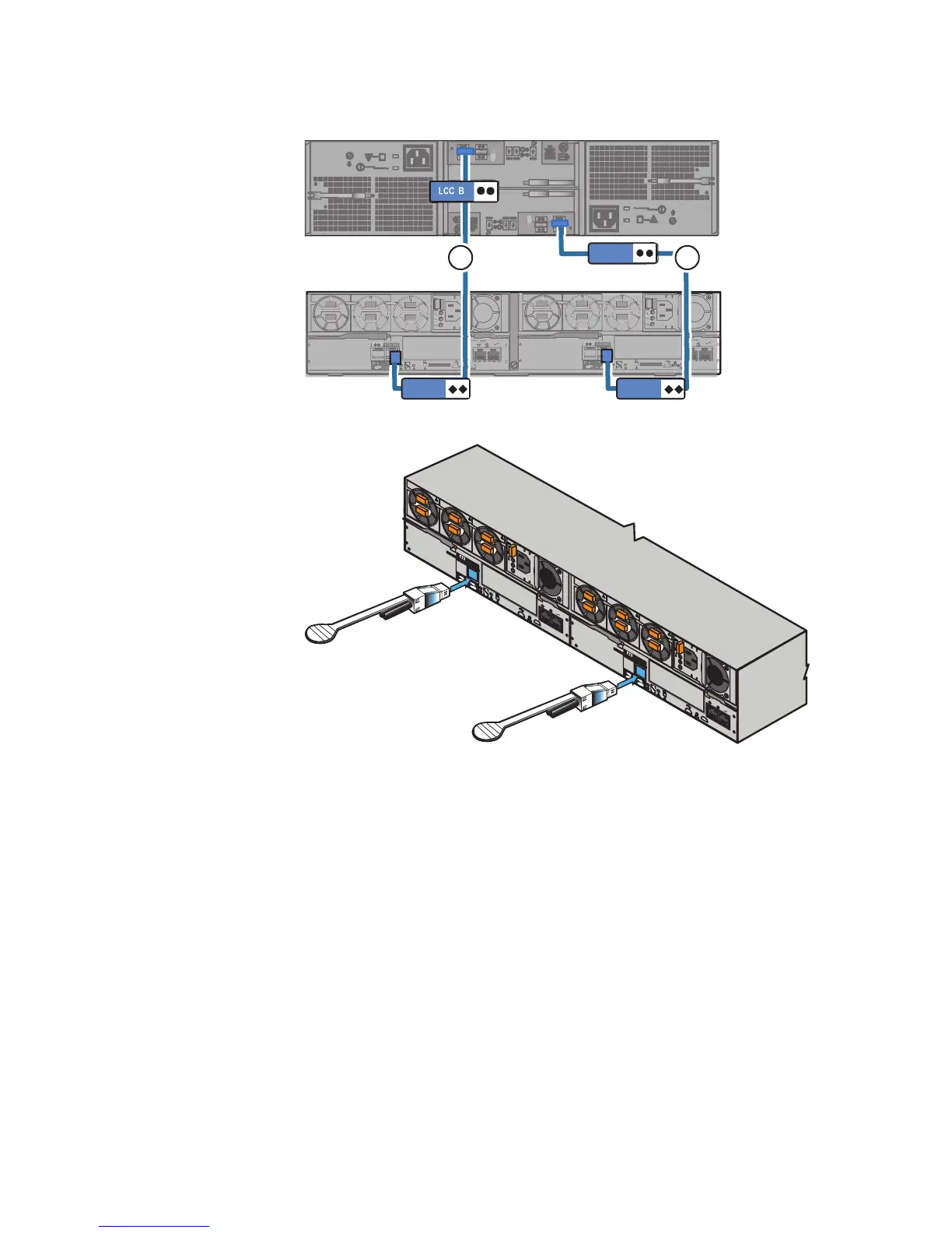
7. (optional) Connect SP B SAS Port 0 to DAE 2 LCC B. See cable 4.
8. If you have additional DAEs, add labels to the mini-SAS to mini-SAS cables and use
them to extend the loops as shown in Figure 23 on page 31.
Figure 23 on page 31 shows an example of DPE to DAE cabling of a system with 5
optional DAEs in an interleaved arrangement as follows:
l
DAE 5 (Bus 1/Enc 2)
l
DAE 4 (Bus 0/Enc 2)
l
DAE 3 (Bus 1/Enc 1)
l
DAE 2 (Bus 0/Enc 1)
l
DAE 1 (Bus 1/Enc 0)
l
DPE (Bus 0/Enc 0)
For more information about interleaved as well as stacked cabling and buses and
enclosure IDs, refer to the
VNXe3200 Hardware Information Guide
.
Rack and install
30 EMC VNXe2 Series VNXe3200 Installation Guide