122 EMC VNX5400 Hardware Information Guide
Disk-array enclosures
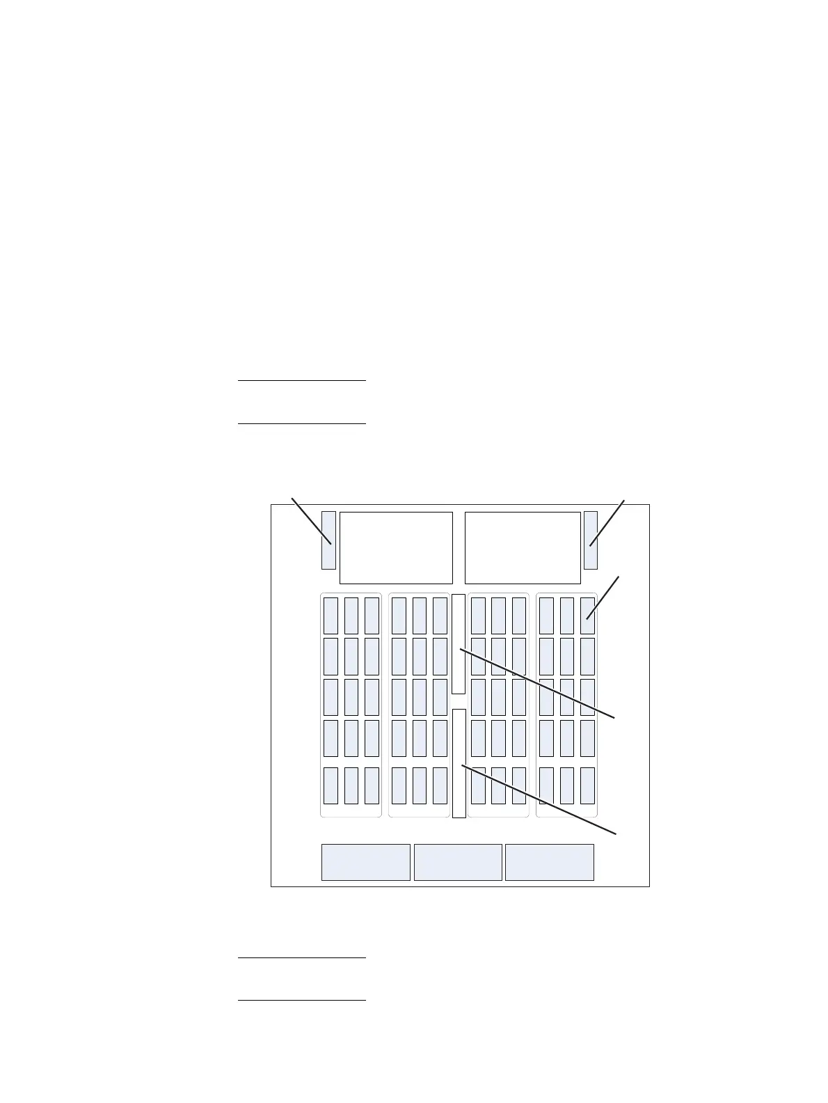
Disk drive layout
Looking at the 4U, 60 (2.5- or 3.5-inch) DAE from the front and above (Figure 102), the
inside of each DAE has physically printed labels located on the left and the front sides of
the DAE. These labels describe the rows (or banks) and the columns (or slots) of where
the disks are installed in the DAE. The banks are labeled from A to E, while the slots are
labeled from 0 to 11.
Rules for disk drive population
The required order of loading the disk drives into a 4U DAE is (Figure 102):
1. Start at row (or bank) A, slot 0.
2. Fill up row (or bank) A before inserting any disk drives into row B.
3. Continue this order until you fill all the rows with row E being the last row filled.
Note: If you partially fill a row, fill the remaining empty slots with filler panel modules.
Rows with no or zero (0) drives do not require filler panel modules.
Figure 102 4U, 60 (2.5- or 3.5-inch) DAE disk drive layout and notation (top-down interior view)
Note: The labels for the banks, slots, and LCCA shown in Figure 102 are the actual labels
in the 4U, 60 (2.5- or 3.5-inch) DAE.
A
B
C
D
E
Rear of 4U DAE
Front of 4U DAE
VNX-000650
0 1 2 3 4 5 LCCA 6 7 8 9 10 11
Cooling Module Cooling Module Cooling Module
Power Supply Module Power Supply Module
Inter Connect Module (ICM) Inter Connect Module (ICM)
Disk drive
LCC B
LCC A

 Loading...


