System component description
EMC VNX5400 Hardware Information Guide 15
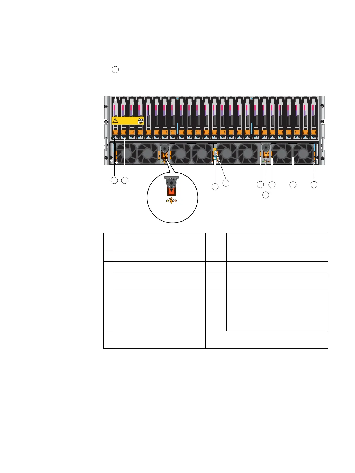
Figure 3 on page 15 shows the location of the disk drives, fan packs, CPU latches, and
status LEDs.
Figure 3 Example of a VNX5400 platform 3U, 25 DPE (front view)
1 Example of a 2.5-inch 6-Gb/s SAS disk
drive
7 DPE fault LED (amber)
2 Dual fan pack fault LED (amber) 8 DPE power status LED (blue)
3 Dual fan pack (two dual packs per SP) 9 Disk drive fault LED (amber)
4 Dual fan pack pull tab (latch, left
side), two places
10 Disk drive status/activity (blue)
5 See Detail Detail SP power/status LED (Green, on); SP fault
LED (amber/blue, various modes - see
“VNX5400 platform 3U, 25 DPE, SP, and
disk drive status LEDs” on page 16 for
more information); Unsafe to remove LED
(white); CPU push/pop latch (two places)
6 Dual fan pack pull tab (latch, right
side), two places
1
G
b
E
01
X4
6Gb SAS
6Gb SAS
23
1
0
1
G
b
E
01
X4
6Gb SAS
6Gb SAS
23
1
0
Will Make the Array Unusable
Caution: Array Software on drives 0-3. Removing or relocating them
A
B
SP
SP
3
6
1
4
5
7
8
Blue/amber
fault
Green on
White
Unsafe to remove
910
Detail
2
0 1
0 1
VNX-000520

 Loading...


