System component description
EMC VNX5400 Hardware Information Guide 19
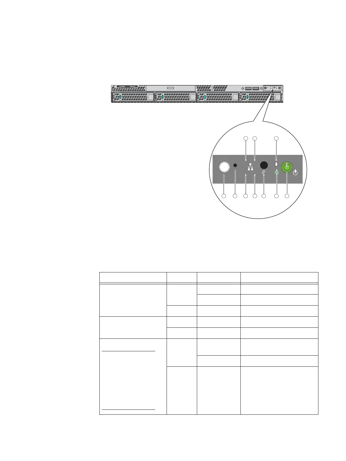
Control Station front panel
Figure 6 shows the location of the File/Unified VNX5400 platform 1U Control Station front
panel.
Figure 6 VNX5400 platform Control Station front panel
Table 4 describes the Control Station front panel.
VNX-000549
Front
45
ID
31 2
678910
Table 4 Control Station LEDs and push buttons
LED Color State Description
Onboard (integrated) LAN 2
and 4 (see locations 1 and
2, respectively)
Green On NIC link/no access
Blinking NIC link/LAN access
—Off Idle
Internal hard drive activity
(see location 3)
Green Blinking Hard drive access
— Off No hard drive activity, no fault
Power (see location 4)
Note: For correct power up
and down procedures, go to
https://mydocs.emc.com/
VNX/ and go to the VNX
tasks section, then select
Power up and down VNX.
Next, follow the steps in the
wizard.
Green On Power on/system loaded and
ready
Blinking Sleep mode
—Off Power off

 Loading...


