System component description
EMC VNX5400 Hardware Information Guide 31
Storage processor power supply module
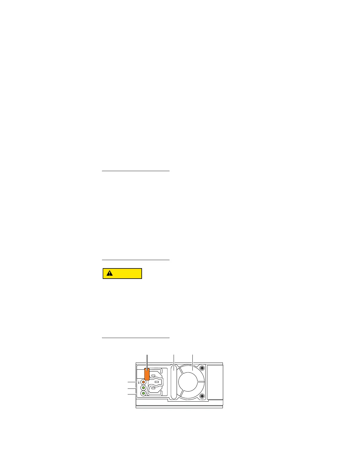
Figure 15 shows the storage processor (SP) power supply module located on the top, right
side of each SP base module enclosure when viewed from the rear. Each power supply
includes three status LEDs (AC, DC, and DC fault). A latch on the power supply locks it into
place to ensure proper connection.
Storage processor power supply types — Three SP power supply modules are supported
in the VNX5400 storage system. They are:
◆ AC Power supply; 200-240 V
◆ AC Power supply; 100-240 V
◆ DC Power supply
Refer to the
VNX5400 Parts Location Guide
for the correct part numbers.
For VNX5400 systems with the 200-240 V AC power supply (models
VNX54DPxxx/VNXB54DPxxx), at least two 200-240 V AC circuits are required for higher
availability. For VNX systems with the 100-240 V AC power supply (model VNX54VPxxx), at
least two 100-240 V AC circuits are required for higher availability. For full power
specifications, go to https://mydocs.emc.com and select View technical specifications
under the About VNX section.
For VNX models with the DC power supply, see the requirements in the
DC-Powered VNX
Series Enclosures Installation and Operation Guide
. For full power specifications, go to
https://mydocs.emc.com and select View technical specifications under the About VNX
section.
Do not
remove the SP power supply module while the SP is plugged in. Power supply
module removal for more than a few minutes can cause the SP to shut down due to lack of
cooling. Refer to the
Replacing a Power Supply (PS) in a DPE
procedure for the correct
steps to take before and during removal of an SP power supply module assembly from
the base module enclosure in a DPE. This procedure is available online at
https://mydocs.emc.com/VNX/ and go to VNX tasks, then select Replace VNX hardware.
Next, follow the steps in the wizard.
Figure 15 SP latch, AC power supply (power in) recessed connector (plug), and status LEDs
AC
DC
Fault LED
DC LED
AC LED
Lever Handle Fan

 Loading...


