32 EMC VNX5400 Hardware Information Guide
System component description
Note: The LED labels on the SP power supply are upside down.
The power supply used in your VNX5400 storage system must meet the storage system
power requirements and must be the same type of power supply to be used in both SPs
(SP A and B). You cannot mix power supply types (see the example part numbers in
Table 9 of the
VNX5400 Parts Location Guide
. For example if you have part number
071-000-022-00 in SP A, the same part number 071-000-022-00 must be in SP B.
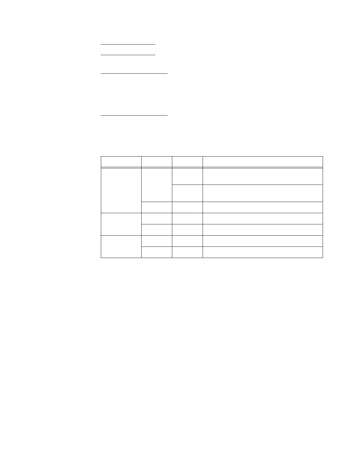
Table 12 describes the power supply (fault and power on) LEDs.
Storage processor management module
The storage processor (SP) management module provides the management connections
via one 10/100/1000 Ethernet (RJ-45) port. Another RJ-45 port is available to support a
service laptop connection. The SP management module includes two RS-232/EIA 232
(DB-9) serial socket connectors (one for service laptop connection and the other for an
SPS connection, not used in the VNX5400 platform), a USB port (not used), and several
LEDs (Figure 16 on page 33).
Table 12 SP power supply (fault and power on) LEDs
LED Color State Description
Fault Amber On Power supply or backup fault, check cable
connection
Blinking BIOS, POST and OS booting up or system
overheating
— Off No fault or power off
DC power
(output)
Green On DC Power on
— Off DC Power off, verify source power
AC power
(Input)
Green On AC Power on
— Off AC Power off, verify source power

 Loading...


