Disk-array enclosures
EMC VNX5400 Hardware Information Guide 93
Rear view
On the rear, the 3U, 120 (2.5-inch) DAE includes two LCCs (A and B) and four power supply
modules (Figure 70).
Figure 70 Example of a 3U, 120 (2.5-inch) DAE with two LCCs (A and B) and four power supply
modules (locations A0, A1, B0, and B1)
The 3U, 120 (2.5-inch) DAE supports one type of power supply module: a dual DC output
power supply. Figure 70 shows the dual DC output power supplies having an orange knob
to install and remove the power supplies to and from the enclosure.
Power supply module
As shown in Figure 70, the power supply module is described in the following paragraphs.
For more information about the technical specifications of the single and the dual output
power supplies, go to https://mydocs.emc.com/VNX/, select View technical
specifications. Next, follow the steps in the wizard for your desired technical
specification. For information about replacing a power supply module, go to
Replacing a
power supply module in a 120-disk enclosure
procedure available online at
https://mydocs.emc.com/VNX/ and go to VNX Tasks,
then select Replace VNX hardware.
Next, follow the steps in the wizard.
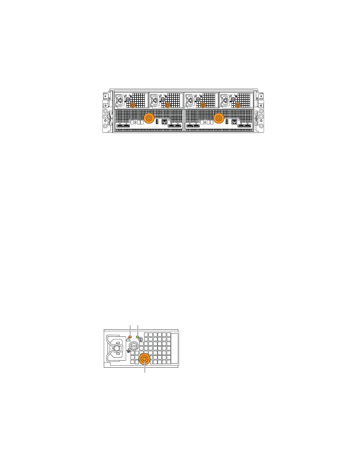
Dual DC output, knob-type power supply
The dual DC output, knob-type power supply (Figure 71) includes two status LEDs: a fault
LED and a power LED. The dual output version is rated at 1080 W with two 12-V DC
outputs (540 W each) and one AC input per power supply. Table 43 on page 94 describes
the LEDs.
Figure 71 Example of a 3U, 120 (2.5-inch) DAE DC dual output, knob-type power supply module
(rear view)
LCC ALCC B
A0B0 B1 A1
Fault LED
Knob
Power LED

 Loading...


