94 EMC VNX5400 Hardware Information Guide
Disk-array enclosures
LCC
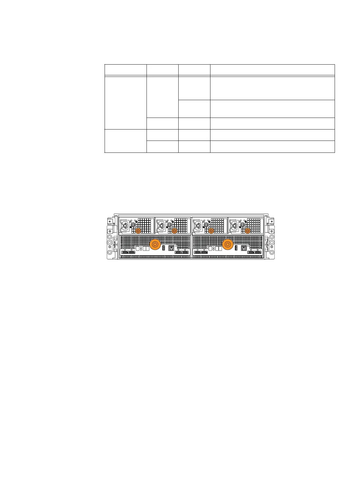
Figure 72 shows an example of the rear view of a 3U, 120 (2.5-inch) DAE showing LCC A
and B with dual output power supplies.
Figure 72 Example of a 3U, 120 (2.5-inch) DAE showing LCC A and B (rear view)
Each LCC (Figure 73 on page 95) provides 4x mini-SAS small form-factor 8088 (SFF-8088)
specification connectors (Figure 74 on page 96). These ports are connected to a SAS
expander with 36 PHYs. The expander allows for traffic to pass through the enclosure
upstream and downstream. It also provides access to the disk drive SAS sub-system. This
disk drive sub-system is made up of four 36 PHY edge expanders in parallel. Each
expander provides SAS connectivity to 30 disk drives. These edge expanders connect to
the fanout expander (IO expander) through a five lane SAS wide port. For information
about replacing an LCC, go to the
Replacing an LCC in a 120-disk enclosure
procedure.
Table 43 3U, 120 (2.5-inch) DAE dual DC output, knob-type power supply (fault and power on) LEDs
LED Color State Description
Fault Amber On Fault, under LCC control. Fans or outputs are
outside the specified operating range while the unit
is in low power mode.
Blinking External fault, under LCC control. 12 VDC off due to
all LCCs not being present.
— Off No fault or power off
Power Green On AC Power on
— Off AC Power off, verify source power
LCC ALCC B
A0B0 B1 A1

 Loading...


