DPSI BMS Operating Manual Version 1.0
Page 11 of 32
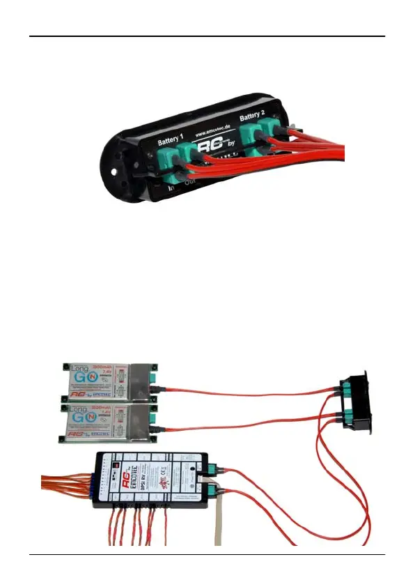
Connector clamping with bracket:
When using battery switches, the DPSI BMS is simply put in between
the batteries and the battery switch. This means: both batteries are
disconnected from the battery switch and connected to the inputs of
the DPSI BMS. The DPSI BMS outputs are then connected to the twin
power supply (e.g. a DPSI RV system) using appropriate patch cables
(e.g. out of the accessory set).
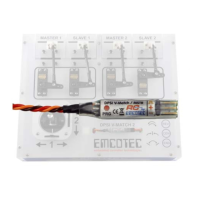
Abmessungen des DPSI BMS: