DPSI BMS Operating Manual Version 1.0
Page 13 of 32
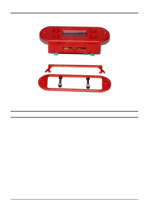
7. Soldering of the Battery Connectors
In case connector cables are manufactured by the user for connection
to the DPSI BMS, correct implementation must be observed. The MPX
high current connectors are marked + and – on their soldering side.
This marking must be strictly observed! The cables are first stripped
(approx. 5 mm / 0.2”) and then tin-plated. Before soldering the cables
to the connectors don’t forget to put the shrink hoses to the cable ends.
The cable is then soldered to all 3 pins, so it is located in their midst
(see photo). When using thin cables, the 3 pins can be bend to their
center (see photo). Sufficient tin has to be provided in order to connect
the cable to all 3 pins. The shrink hoses are then shrunk using a heat
gun.