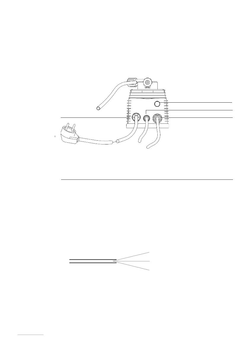
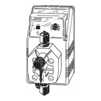
External signal input
Power supply Level probe input
How to
connect the
pump
Connect the “BNC” of the external signal to the “INPUT” connector.
SCREEN (CABLE BRAID): -
CENTRAL CONDUCTOR: +
This signal can be used in one of the following modes:
-
Meter
-
Batch mode start contact
-
Voltage input volt mode
-
Current input mA
-
Stand-by input in Constant mode
Fig. 9. Pump connections
Pulse water
meter with
HALL effect
The version of the dosing pump for connection to a HALL effect pulse water
meter has a 3-wire cable at the external signal input (figure 11).
If the Hall effect pulse water meter is supplied by the manufacturer, the external
signal input will have an MPM connector to which to connect the meter.
For connections on the circuit, see ⎘"Circuit diagram.
Fig. 10. External signal cable for pulse water meter
white - signal
yellow - ground
brown - + 12V
External signal input
Out alarm
red: +
black: -
LEVEL ALARM OUTPUT (option)
If present, connect the red/black wire.
Clean contact not protected by a fuse.
Maximum load: 1A 115 VAC.


 To Next Page