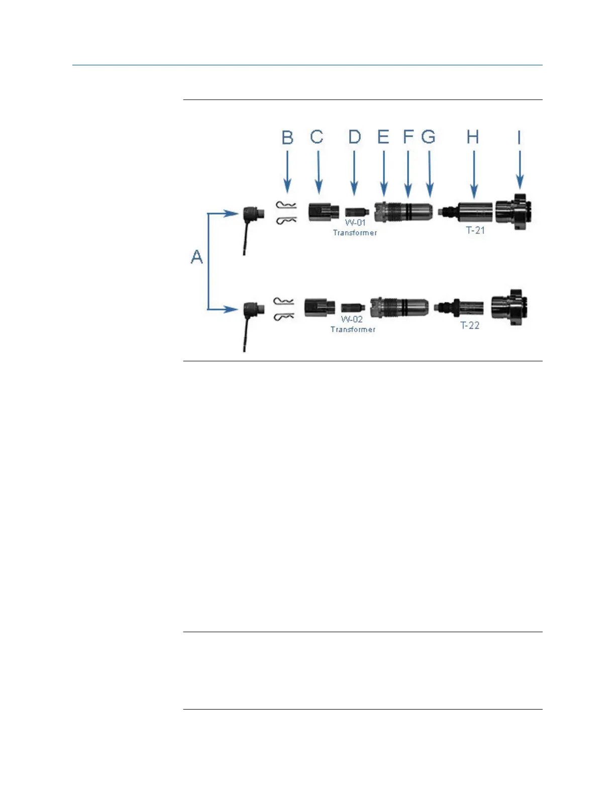
Figure 3-1: T-21 and T-22 transducer assembly
A. Transducer cable (max. length 15 ft.)
B. Retainer clips
C. Transformer retainer (Standard P/N 1-360-01-958 or High Temperature P/N
1-360-01-978)
D. Transformer module T-21/T-41 (W-01 P/N 1-360-03-090) or T-22 (W-02 P/N
1-360-03-110)
E. Transducer holder
F. Transducer holder O-rings and backer rings
G. Transducer holder set screws
H. Transducer assembly
I. Mount comes with o-ring and backer ring
5. Loosen the T-Slot transducer holder assembly with a 1 1/4” socket. Carefully
remove the T-Slot transducer assembly.
6. Loosen the three Allen setscrews with a 1/16” hex driver securing the transducer
assembly and stalk, if installed. Carefully remove the old transducer by pulling it
from the T-Slot transducer holder assembly without rotating.
Important
Record the “L” dimension of the removed transducers which is used to update the
meter configuration after all of the transducers are replaced. Make sure you have
the report sheet containing the “L” dimension, Delay Time, and Delta Delay Time
for the replacement pair of transducers to use during the Transducer Swap-out
procedure in Daniel MeterLink.
Meter repairs Maintenance and Troubleshooting manual
August 2021 P/N 3-9000-791
46 Models 3415, 3416 and 3417 GUSM

 Loading...


