7. Clean the transducer holder with a dry cloth.
3.2.2 T-Slot transducer installation
Procedure
1. Ensure that the Daniel 3410 Series Ultrasonic Gas Flow Meter transducer port,
mount, and T-Slot transducer holder assembly are clean and free of debris.
2. Apply a small amount of Molykote 111 to the female contacts on the transducer.
3. Install the transducer assembly into the transducer holder or into the stalk (if
required). The parts are keyed and can only be assembled one way. As the
transducers are installed into the holder or stalk assembly, they must be labeled
with a marker for future reference (i.e., transducer #1 would be A-1 and transducer
#2 would be A-2).
4. Use a 1/16” hex driver to equally tighten the three Allen set screws on the
transducer holder to secure the transducer assembly and the stalks (if installed).
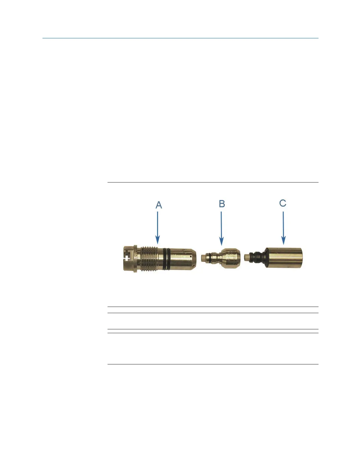
Figure 3-2: Transducer holder, stalk and transducer assembly
A. Transduce holder
B. Stalk
C. Transducer assembly
Note
Do not apply lubricant to the transducer or stalk O-rings.
NOTICE
Ensure that the transducers identified as belonging to end 1 are installed on end 1
of the meter housing and those identified as belonging to end 2 are installed on end
2 of the meter housing.
5. Replace the O-ring and Backup O-ring on the transducer holder. It is highly
recommended that the O-rings be replaced when the transducer is removed from
the holder or stalk. Ensure that the contoured side of the backer ring is facing
toward the transducer capsule attached to the end of the transducer holder.
Lubricate with Molykote 111 Silicone Grease or equivalent.
Maintenance and Troubleshooting manual Meter repairs
P/N 3-9000-791 August 2021
Maintenance and Troubleshooting manual 47

 Loading...


