Note
Replacing the O-rings at this point minimizes the chances of damaging the
transducer by dropping it.
6. Apply a small amount of nickel anti-seize (N.A.S.) compound (P/N 2-9-9960-134) to
the outer threads of the transducer holder (see Figure 3-2).
7. Carefully install the transducer holder assembly into the transducer mount. Make
sure the threads of the holder and mount are correctly aligned. Use a 1 ¼” socket
and screw the transducer assembly into the mount. Tighten to securely seat the
assembly in the mount. Do not over tighten (see #unique_46/
unique_46_Connect_42_fig_sym_lzl_cmb).
8. Install the keyed transformer module into the transducer holder (see #unique_46/
unique_46_Connect_42_fig_sym_lzl_cmb).
a) Apply a small amount of Molykote 111 to the transformer module O-ring.
b) Insert the keyed transformer module into the back end of the transducer
holder.
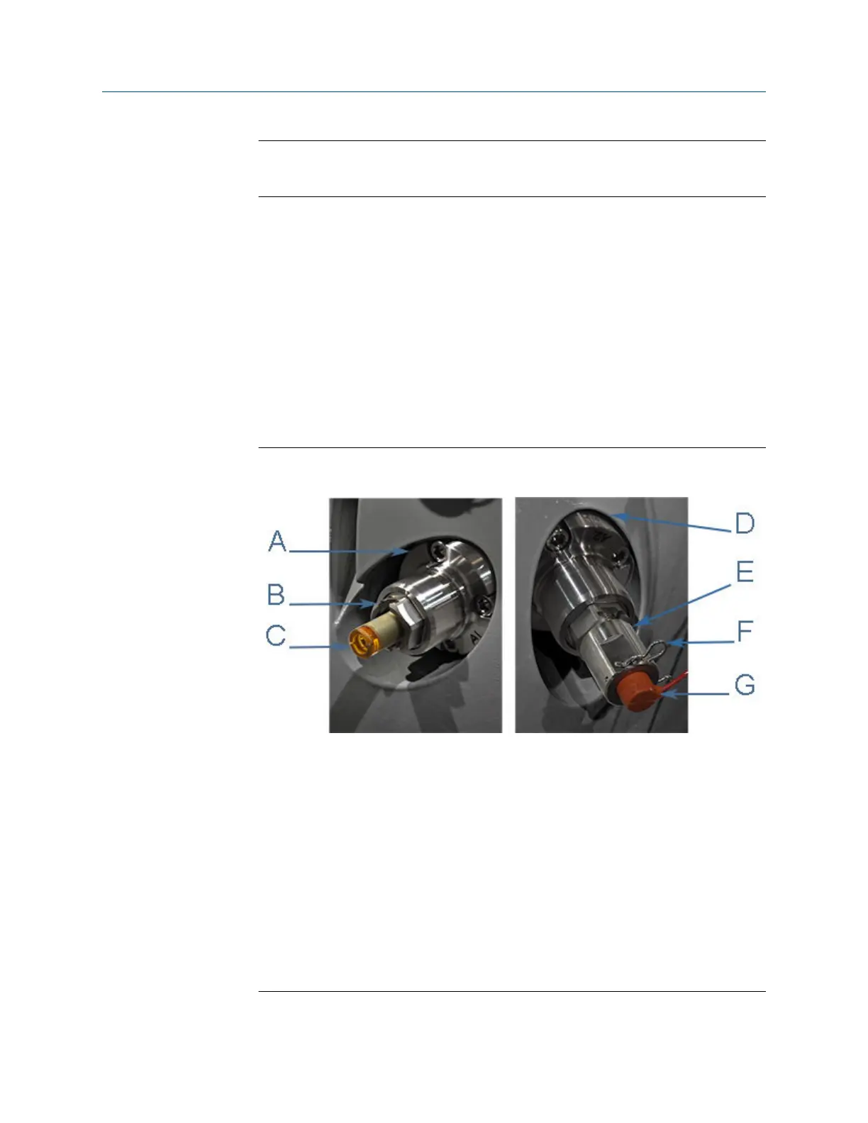
Figure 3-3: T-21 and T-22 transducer assembly, holder, transformer assembly,
retainer, retaining clip and transducer cable
A. Mount (Inconel mount and holder)
B. Transducer holder (Type - H1 P/N 1-360-01-128, H2 P/N 1-360-01-228)
C. T-21 transformer module (W-01 P/N 1-360-03-090) or T-22 transformer module
(W-02 P/N 1-360-03-110)
D. Transducer port (meter body)
E. Transformer retainer (P/N 1-360-01-160)
F. Retaining clip
G. Transducer cable:
• 100°C - 5’ length P/N 1-360-03-232)
• 100°C -15’ length (P/N 1-360-03-233)
Meter repairs Maintenance and Troubleshooting manual
August 2021 P/N 3-9000-791
48 Models 3415, 3416 and 3417 GUSM

 Loading...


