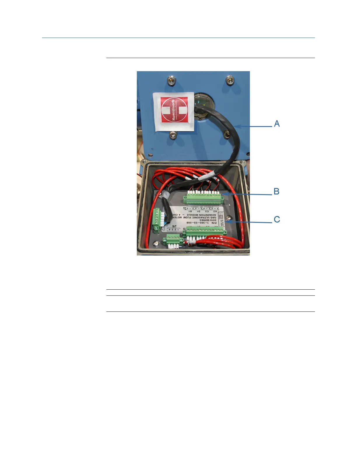
Figure 3-31: Acquisition Module cable and transducer wiring
A. Acquisition cable
B. Acquisition wiring terminal blocks
C. Acquisition Module
NOTICE
Ensure the transducer cables are labeled for the chord configuration.
6. Remove the three Acquisition Module flat head screws and split lock washers, then
remove the Acquisition Module from the Base Enclosure.
7. Insert the new Acquisition Module into the Base Enclosure and secure with the three
split lock washers and flat head screws.
8. Reattach the terminal blocks onto the Acquisition Module (3 mm flat head screw
driver required). Ensure the transducer wires have good contact with the terminal
block and the terminal block screws are tight.
9. When you have completed attaching the Transducer wire terminal blocks and the
Acquisition cable terminal block to the Acquisition Module, check the Base
Enclosure o-ring and reinstall if necessary.
10. Reattach the Transmitter Electronics Enclosure to the Base Enclosure with the four
hex head bolts and lock washers. Tighten bolts with a 6mm Allen wrench.
Meter repairs Maintenance and Troubleshooting manual
August 2021 P/N 3-9000-791
86 Models 3415, 3416 and 3417 GUSM

 Loading...


