Function principle
[12]
Note
If installing a calibrated measuring chain at a different measuring point, ensure that the target
material of this point is the same as of the previous point. Otherwise, recalibrate the converter on the
new target material.
4.1
Sensor supervision
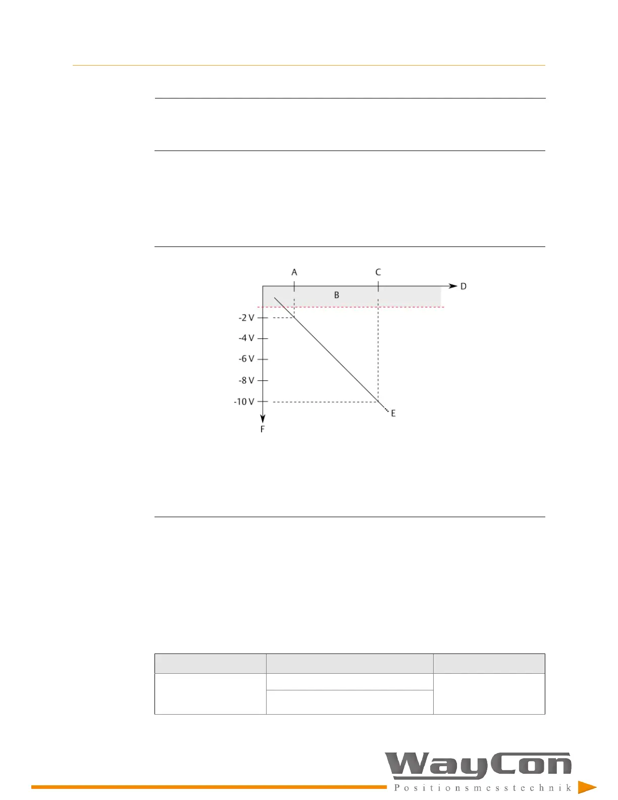
The EZ 1000 checks the connected sensor by supervising the signal voltage. A sensor not
OK indication is displayed when the sensor OK limit of -1.5 V has been violated.
Figure 4-2: Diagram sensor supervision
A.
Beginning of the measuring range (smallest distance to measuring object)
B.
Sensor not OK area. Limit: -1.5 V
C.
Mid of measuring range
D.
Distance between sensor and measuring object
E.
Voltage output curve (-2 to -18 V)
F.
Output voltage
Sensor not OK indication:
•
Green LED on the converter front is switched off (see
Table 3-1
).
The green LED is used for sensor, voltage, and converter fault indication.
•
Sensor state in the online view of Machine Studio indicates a fault (see
Section 9.1
).
Table 4-1
lists causes for a sensor not OK indication.
Table 4-1: Causes for sensor not OK indication
Cause
Possible reasons
Solution
Sensor is too close to the
measuring object.
Machine behavior has been changed. Check the distance and
readjust the sensor
position if necessary.
Loosened sensor holder.

 Loading...