[8]
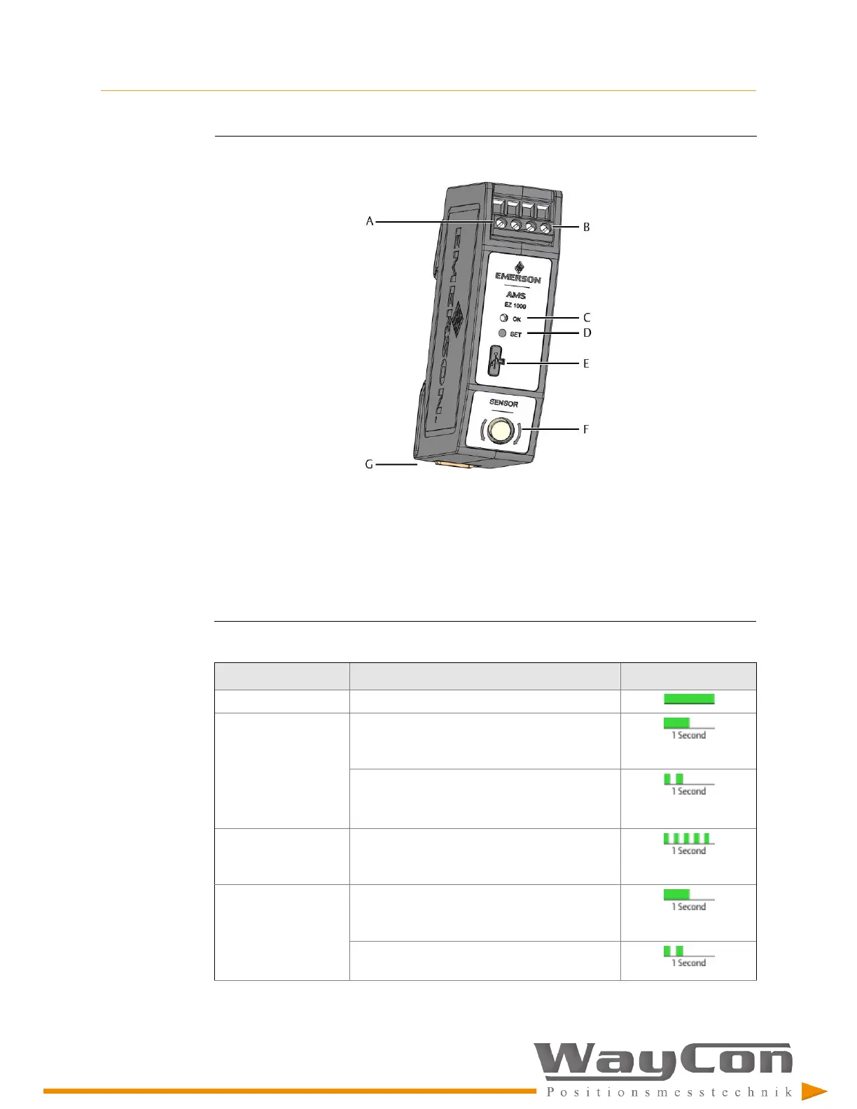
Figure 3-1: EZ 1000
A.
Two screw terminals for -24 V DC supply voltage.
B.
Two screw terminals for sensor output signal (range: -2 V to -18 V)
C.
Green Channel OK LED (see Table 3-1)
D.
Button for offline calibration (Easy calibration) without Machine Studio and for Firmware update
E.
Configuration interface (USB 2.0 Micro-B socket with cover)
F.
Sensor socket with external thread for sensor connection
G.
Build-in spring DIN rail clip
Table 3-1: LED blinking pattern
Event
Blinking pattern
Sequence
(1)
Normal operation Steady green light
Offline (Easy)
calibration
Slow flashing (1 Hz) for approximately 5
seconds; request of calibration – before
measurement
Double flashing (1 Hz) for approximately 5
seconds during measurement
(see
Section 8.7
for details)
Offline (Easy)
calibration – failure
detected
Unlimited fast flashing (5 Hz) – until power off/
on the EZ 1000
Automatic calibration
with Machine Studio
Slow flashing (1 Hz) for approximately 5
seconds; request of calibration – before
measurement
Double flashing (1 Hz) for approximately 5
seconds during measurement

 Loading...