44 Chapter 5 Parameter Introductions
EV2000 Series Universal Variable Speed Drive User Manual
Use terminals FWD, REV, JOGF and JOGR to start and
stop the drive.
2: Serial port control: Input commands via serial port
Use serial port to start and stop the drive.
Notes
Please be careful that during operating, the control modes
can be changed through F0.03 or external terminals or
PANEL/REMOTE key.
F0.04 Set running direction
Range: 0, 1 【0】
This function is active in panel control mode and serial
port control mode, and inactive in terminal control mode.
0: Forward
1: Reverse
F0.05 Max output
frequency
Range: Max{50.00,F0.12 upper
limit of frequency}~650.00Hz
【50.00Hz】
F0.06 Basic
operating frequency
Range:1.00~650.00Hz 【50.00Hz】
F0.07 Max output
voltage
Range:1~480V 【drive’s rating
values】
Max output frequency is the highest permissible output
frequency of the drive, as shown in Fig. 5-2 as f
max
;
Basic operating frequency is the Min frequency when
the drive outputs the max voltage, as shown in Fig. 5-2
as f
b
Max output voltage is the drive’s output voltage when
the drive outputs basic operating frequency, as shown in
Fig. 5-2 as V
max
f
max
Output
voltage
f
b
f
H
f
L
Output
frequency
V
max
Fig. 5-2 Characteristic parameters
The f
H
and f
L
are defined by F0.12 and F0.13 as upper
limit of frequency and lower limit of frequency
respectively.
Note:
Please set fmax, fb and Vmax according to motor
parameters, otherwise the equipment may be damaged.
F0.08 Drive type selection
Range:0. 1【0】
0: Type G (load with constant torque)
1: Type P (fan & pump load)
EV2000 series drive of 45kW or below uses the type G
and type P integrated mode. The power of motor
matched with the drive type G is lower than that of type
P. Please refer to Table 2-2 for details.
The factory setting of the drive is set to type G.
For example: EV2000-4T0055G/0075P drive’s factory
setting is 5.5kW type G drive. If the drive needs to be
changed to 7.5kW type P drive, then:
①set this parameter to 1
②set group FH parameters again
Note:
Follow the same procedures if the drive needs to be
changed from type P to type G.
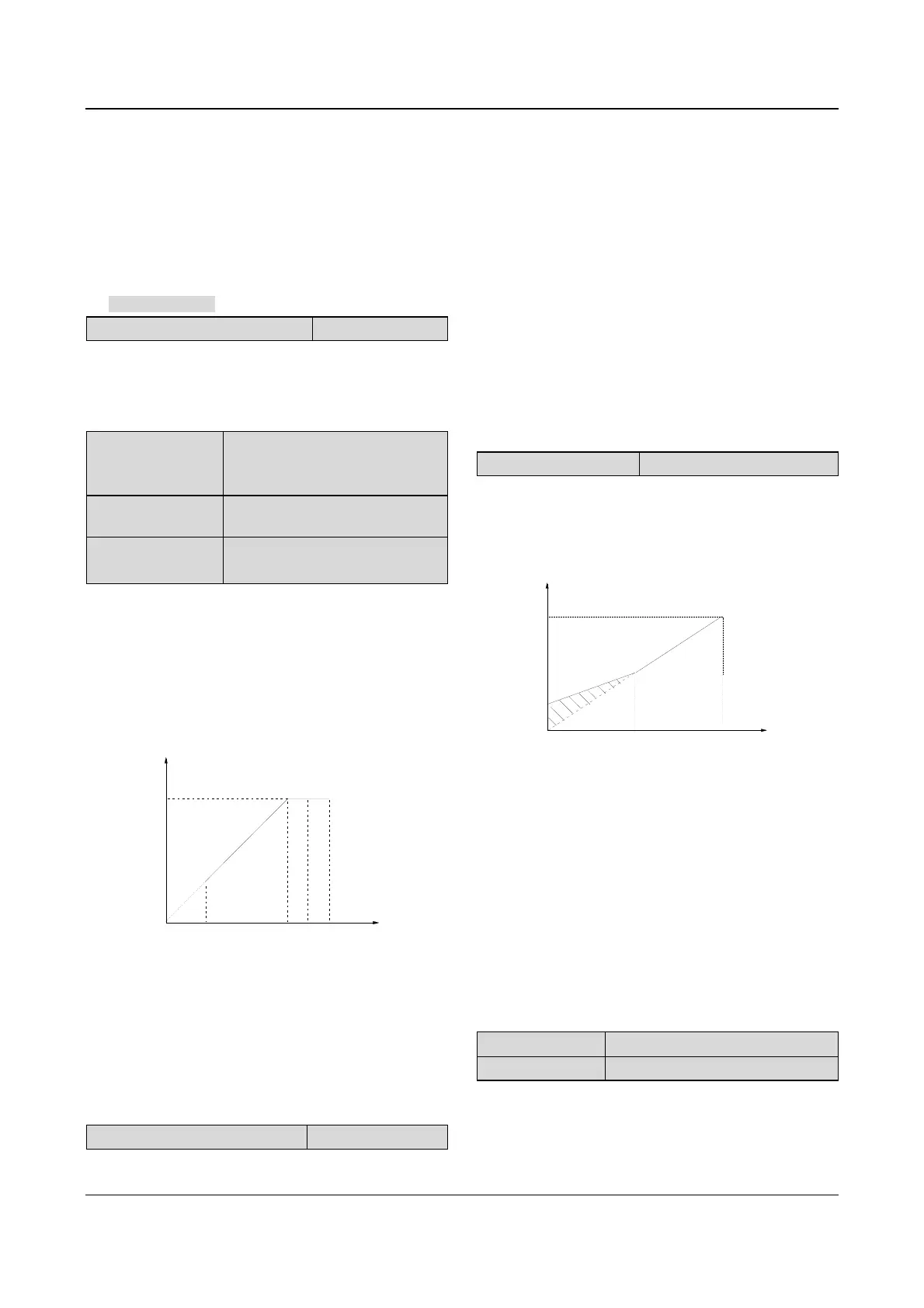
F0.09 Torque boost
Range:0~30.0%【0.0%】
In order to compensate the torque drop at low frequency,
the drive can boost the voltage so as to boost the torque.
If F0.09 is set to 0, auto torque boost is enabled and if
F0.09 is set non-zero, manual torque boost is enabled,
as shown in Fig. 5-3.
: Manual torque boost Vmax: Max output voltage
: Cut-off freq. for torque boost
: Basic operating freq.
Output
voltage
f
b
V
b
V
max
Output
freq.
f
z
V
b
f
z
f
b
Fig. 5-3 Torque boost(shadow area is the boosted
value)
Note:
1. Wrong parameter setting can cause overheat or
over-current protection of the motor.
2. Refer to F0.21 for definition of fz.
3. When the drive drives a synchronous motor,torque boost
function is recommended to be used and V/F curve should
be adjusted according to the motor parameters.
F0.10 Acc time 1
Range:0.1~3600s(min)【6.0s/20.0s】
F0.11 Dec time 1
Range:0.1~3600s(min)【6.0s/20.0s】
 Loading...


