Chapter 5 Parameter Introductions 45
EV2000 Series Universal Variable Speed Drive User Manual
Output
frequency
t
1
f
max
t
2
Time
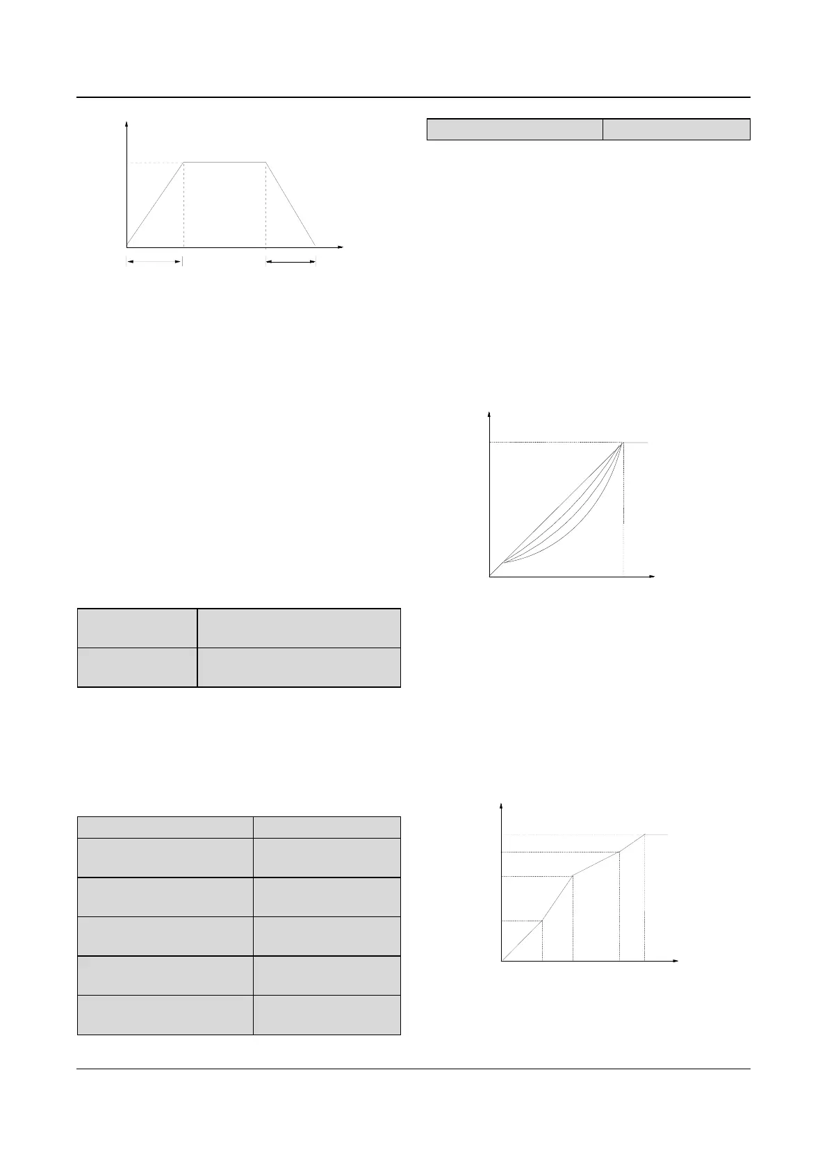
Fig. 5-4 Acc/Dec time definition
Acc time is the time taken for the motor to accelerate
from 0Hz to the maximum frequency (as set in F0.04),
see t
1
in Fig. 5-4.
Dec time is the time taken for the motor to decelerate
from maximum frequency (F0.05) to 0Hz, see t
2
in Fig.
5-4.
EV2000 series drive has defined 4 kinds of Acc/Dec
time. Here only Acc/Dec time 1 is defined, and Acc/Dec
time 2~4 will be defined in F3.17~F3.22, please refer to
section 5.4.
Note:
1. Unit(second/minute) of Acc/Dec time 1~4 is dependent
on the setting of F9.09, and the default unit is second.
2. For the drive of 30kW or above, the factory setting of
Acc/Dec time is 20.0s.
F0.12 upper limit of
frequency
Range: Lower limit of frequency
~Max output frequency【50.00Hz】
F0.13 lower limit of
frequency
Range:0~upper limit of frequency
【0.00Hz】
F0.12 and F0.13 define the upper and lower limit of
frequencies respectively, as shown in Fig. 5-2 as f
H
and
f
L
.
Notes:
Actual output frequency is possible to exceed ±2.5Hz in
the bus-voltage control process.
F0.14 V/F curve setting
Range: 0~3【0】
F0.15 V/F frequency value F3
Range: F0.17~F0.06
【0.00Hz】
F0.16 V/F voltage value V3
Range: F0.18~100.0%
【0.0%】
F0.17 V/F frequency value F2
Range: F0.19~F0.15
【0.00Hz】
F0.18 V/F voltage value V2
Range: F0.20~F0.16
【0.0%】
F0.19 V/F frequency value F1
Range: 0~F0.17
【0.00Hz】
F0.20 V/F voltage value V1
Range:0~F0.18【0.0%】
This group of parameters define the V/F setting modes
of EV2000 so as to satisfy the requirements of different
loads. 3 preset curves and one user-defined curve can
be selected according to the setting of F0.14.
If F0.14 is set to 1, a 2-order curve is selected, as shown
in Fig. 5-5 as curve 1;
If F0.14 is set to 2, a 1.7-order curve is selected, as
shown in Fig. 5-5 as curve 2;
If F0.14 is set to 3, a 1.2-order curve is selected, as
shown in Fig. 5-5 as curve 3;
The above curves are suitable for the variable-torque
loads such as fan & pumps. You can select the curves
according to the actual load so as to achieve best
energy-saving effects.
0
1
Output voltage (V)
Output frequency (Hz)
2
3
f
: Max output voltage(F0.07)
: Basic operating frequency(F0.06)
0
V
max
V
max
f
b
b
Fig. 5-5 Torque-reducing curve
If F0.14 is set to 0, you can define V/F curve via
F0.15~F0.20, as shown in Fig. 5-6. The V/F curve can
be defined by connecting 3 points of (V1,F1), (V2,F2)
and (V3, F3), to adapt to special load characteristics.
Default V/F curve set by factory is a direct line as show
in Fig. 5-5 as curve 0.
Voltage (%)
Freq Hz
Fb
100%
V1
V2
F1
F2
V3
F3
V1~V3: Voltage of sections 1~3
F1~F3: Freq of sections 1~3
Fb: Basic operating freq. of F0.06
Fig. 5-6 V/F curve defined by user