Chapter 5 Parameter Introductions 53
EV2000 Series Universal Variable Speed Drive User Manual
RUN
command
f
1
f
2
f
3
f
4
f
5
f
6
f
7
T
1
T
2
T
3
T
4
T
5
T
6
T
7
a
1
a
2
a
3
d
3
a
4
d
5
a
5
a
6
d
7
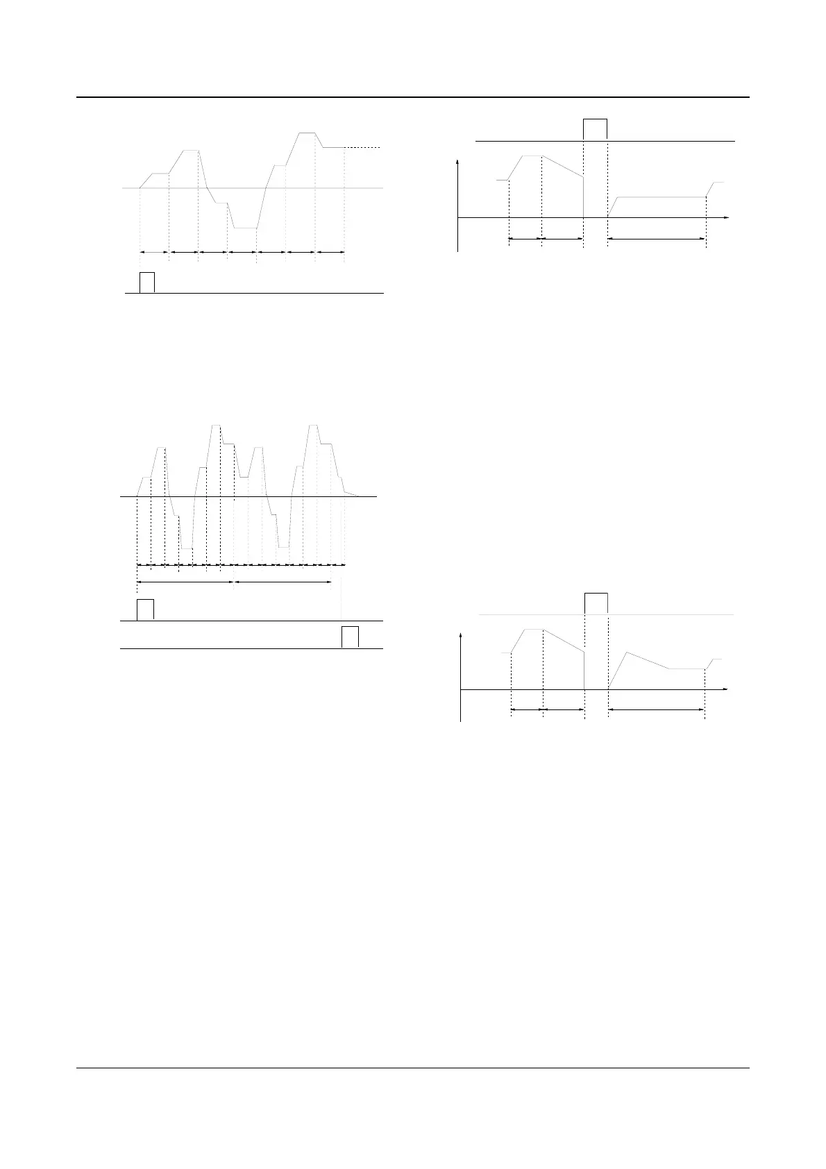
Fig. 5-24 Maintaining the frequency after single cycle
3 (continuous operation): See Fig. 5-25, the drive will
start next cycle of operation automatically after
completing one cycle of operation until receiving STOP
command.
RUN
command
STOP
command
f
1
f
2
f
3
f
4
f
5
f
6
f
7
T
1
PLC
operation
f
1
f
2
f
3
f
4
f5
f6
f
7
f
1
d
1
d
1
d
2
First cycle
Second cycle
...
T
2
T
3
T
4
T
6
T
5
T
7
T
1
T
2
T
3
T
4
T
6
T
5
T
7
T
1
Fig. 5-25 Continuous operation of PLC
Tens’ place: Restart after PLC operation pause
0: Operate from first section
If the drive stops during PLC operation due to receiving
STOP command, fault or power failure, it will run from
the first stage after restarting.
1: Continue from the stage where the drive stops
When the drive stops during PLC operation due to
receiving STOP command or fault, it will record the
operating time and will continue from the stage where
the drive stops after restart at the frequency defined for
this stage, as shown in Fig. 5-26.
Stopping signal
...
Stage 1
f
1
a
1
Output freq.Hz
Remnant time of
stage 2
f
2
d
2
a
2
...
f
3
a
3
a
1
: Acc time of stage 1
2
: Acc time of stage 2
a
3
: Acc time of stage 3
2
: Dec time of stage 2
f
1
: Freq. of stage 1
2
: Freq. of stage 2
f
3
: Freq. of stage 3
Operating
time of
stage 2
Time
a
d
f
Fig. 5-26 PLC start mode 1
2: Continue to operate at the frequency when the drive
stops
When the drive stops during PLC operation due to
receiving STOP command or fault, it will record the
operating time and the current frequency. It will continue
running at the recorded frequency from the stage where
it just stops upon restart, as shown in Fig. 5-27.
Note:
The difference between mode 1 and mode 2 is that in mode
2, the drive can record the operating frequency when the
drive stops and will run at the recorded frequency after
restart.
a
1
: Acc time of stage 1
2
: Acc time of stage 2
a
3: Acc time of stage 3 2 : Dec time of stage 2
f
1
: Freq. of stage 1
2 : Freq. of stage 2
f
3: Freq. of stage 3
Stopping signal
...
Stage 1
f
1
a
1
Operating
time of
stage 2
Remnant time of
stage 2
Output freq. Hz
Time
f
2
d
2
a
2
...
f
3
a
3
d
2
a
a
f
Fig. 5-27 PLC starting mode 2
Hundred’s place: Store the PLC status after power
failure
0: Not save
The drive does not save the PLC operating status after
power failure and start operating in first stage after
restart.
1: Save
Memorize the operating parameters of PLC operation
after power failure, including the operating stage,
operating frequency, and operating time. The drive will
continue to operate in the mode defined by the ten’s
place.
 Loading...


