Chapter 5 Parameter Introductions 65
EV2000 Series Universal Variable Speed Drive User Manual
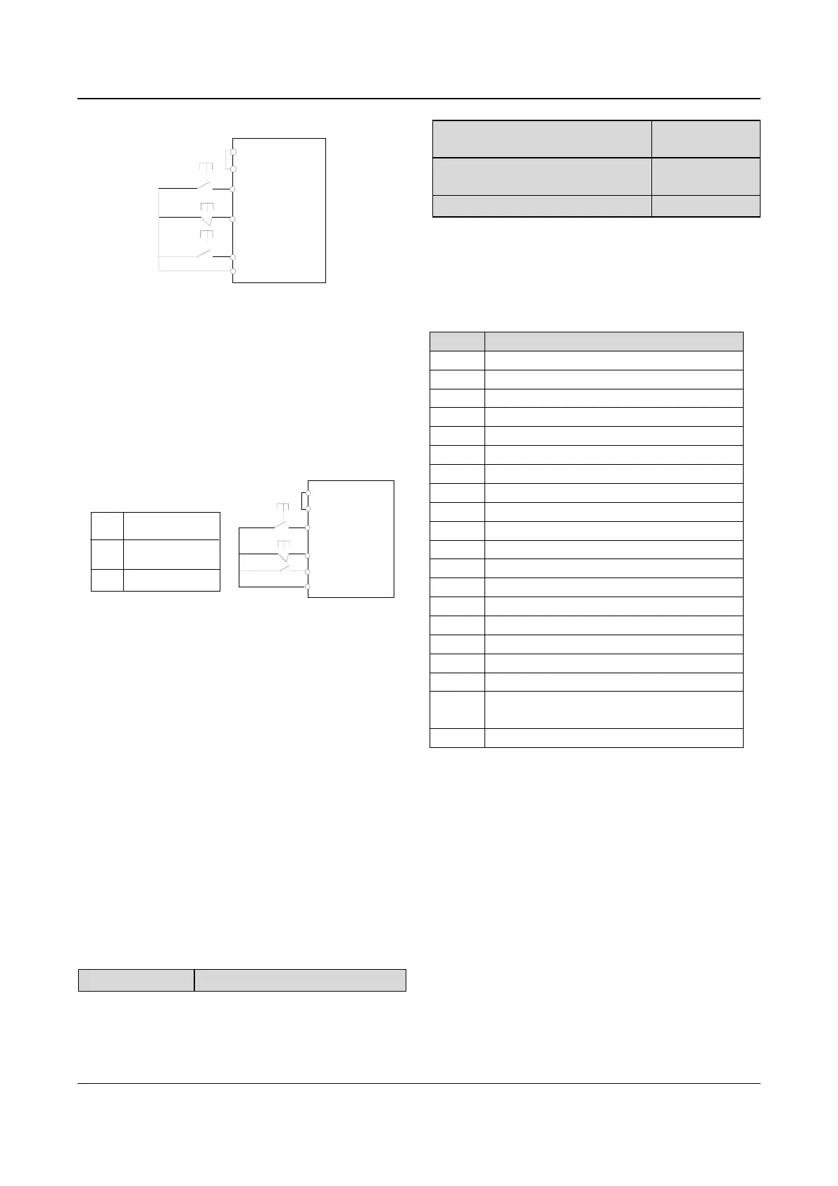
2: 3-wire operating mode 1
FWD
Xi
REV
SB3
COM
SB1
SB2
EV2000
.
.
.
.
PLC
P24
.
.
Fig. 5-44 3-wire operating mode 1
Where:
SB1: Stop button
SB2: Run forward button
SB3: Run reverse button
Terminal Xi is the multi-function input terminal of X
1
~X
8
.
At this time, the function of this terminal should be
defined as No.16 function of “3-wire operation”.
3: 3-wire operation mode 2
FWD
Xi
REV
K
COM
SB1
SB2
0
K
1
Running direction
Forward
Reverse
EV2000
.
.
.
.
PLC
P24
.
.
Fig. 5-45 3-wire operating mode 2
Where:
SB1: Stop button
SB2: Run button
Terminal Xi is the multi-function input terminal of X
1
~X
8
.
At this time, the function of this terminal should be
defined as No.16 function of “3-wire operation”.
Note:
In terminal control mode, for 2-wire operating mode 1 and
2, although the terminal is enabled, the drive will not run
forward or reverse when the drive stops due to the STOP
command from terminal function 11 or 35 (see
F7.00~F7.07), PLC stop after single cycle, stop due to the
arrival of fixed length, pressing STOP key. If you need to
start the drive again, enable FWD/REV again. However,
when the drive stops due to a fault, it will start immediately
if the terminal FWD/REV is enabled and the fault is
cleared.
F7.09 UP/DN rate
Range:0.01~99.99Hz/s【1.00Hz/s】
F7.09 is used to define the change rate of reference
frequency that is changed by terminal UP/DN.
F7.10 Bi-direction open-collector
output terminal Y1
Range:0~19【0】
F7.11 Bi-direction open-collector
output terminal Y2
Range:0~19【1】
F7.12 Output functions of relay
Range:0~19【16】
Refer to section 3.3.2 for the output characteristics of Y1
and Y2 that are bi-direction open-collector output
terminal and the relay’s output terminal. Table 5-11
shows the functions of the above 3 terminals. One
function can be selected repeatedly.
Table 5-11 Functions of output terminals
Setting Function
0 Drive running signal (RUN)
1 Frequency arriving signal (FAR)
2 Frequency detection threshold (FDT1)
3 Frequency detection threshold (FDT2)
4 Overload signal (OL)
5 Low voltage lock-up signal (LU)
6 External stopping command (EXT)
7 High limit of frequency (FHL)
8 Lower limit of frequency (FLL)
9 Zero-speed running
10 Completion of simple PLC operation
11 PLC cycle completion indication
12 preset counting value arriving
13 specified counting value arriving
14 preset length arriving indication
15 drive ready (RDY)
16 Drive fails
17 Extended function 1 of host
18
Upper and lower limits of traverse
operating frequency
19 Preset operating time out
In Table 5-11:
0: Drive running signal (RUN)
When the drive is in operating status, there will be
running indication signal output by this terminal.
1: Frequency arriving signal (FAR)
See F7.13.
2: Frequency detection threshold (FDT1)
See F7.14~F7.15.
3: Frequency detection threshold (FDT2)
See F7.16~F7.17.
4: Overload signal (OL)
The terminal outputs the indicating signal if the drive’s
output current is higher than the value defined by FL.05
and the overload time is longer than the time defined by

 Loading...

