66 Chapter 5 Parameter Introductions
EV2000 Series Universal Variable Speed Drive User Manual
FL.06. This function is usually used in overload
pre-alarm. See Fig. 5-74.
5: Low voltage lock-up signal (LU)
The terminal outputs the indicating signal if the DC bus
voltage is lower than the low voltage limit, and the LED
displays “P.oFF”.
6: External stopping command (EXT)
The terminal outputs the indicating signal if the drive
outputs tripping signal caused by external fault (E015).
7: High limit of frequency (FHL)
The terminal outputs the indicating signal if the preset
frequency is higher than upper limit of frequency and the
operating frequency reaches the upper limit of
frequency.
8: Lower limit of frequency (FLL)
The terminal outputs the indicating signal if the preset
frequency is higher than lower limit of frequency and the
operating frequency reaches the lower limit of
frequency.
9: Zero-speed running
The terminal outputs the indicating signal if the drive’s
output frequency is 0 and the drive is in operating status.
10: Completion of simple PLC operation stages
The terminal outputs the indicating signal (pulse signal,
500ms width) if the present stage of PLC operation is
finished.
11: PLC cycle completion indication
The terminal outputs the indicating signal (signal pulse,
500ms width) if one cycle of PLC operation is finished.
12: preset counting value arriving
13: reference length arriving indication
Refer to F7.33~F7.34 for terminals 12 and 13.
14: preset length arrival indication
The terminal outputs the indicating signal if the actual
length defined by F9.15 is longer than the length defined
by F9.14. Function of terminal X1~X8 should be set to
No.44 function.
15: drive ready (RDY)
If RDY signal is output, it means the drive has no fault,
its DC bus voltage is normal and it can receive starting
command.
16: Drive fails
The terminal outputs the indicating signal if the drive has
faults.
17: extended function 1 of host
The output signal of terminal Y1, Y2 or TC is directly
controlled by a serial port. Refer to the communicating
protocol of EV2000.
18: Upper and lower limits of traverse operating
frequency
If traverse operating function is selected, an indicating
signal will be output if the traverse operating frequency
calculated by central frequency is higher than upper limit
of frequency (F0.12) or lower than the lower limit of
frequency (F0.13), as shown in Fig. 5-46.
Before limiting amplitude
Upper limit o
f freq
Lower limit of freq.
T
raverse
operation
Y1:
upper and lower limit
of traverse operation
After limiting amplitude
Central freq.
Fig. 5-46 Traverse operating amplitude control
19: preset operating time out
The terminal outputs the indicating signal if the drive’s
total operating time (Fn.01) reaches preset operating
time (Fn.00).
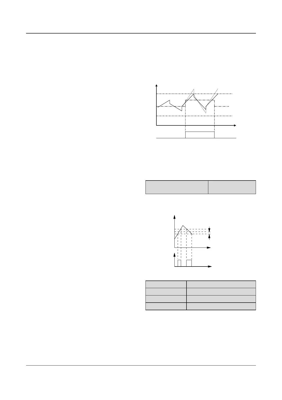
F7.13 Frequency arriving signal
(FAR)
Range:0.00~650.00Hz
【2.50Hz】
As shown in Fig. 5-47, if the drive’s output frequency is
within the detecting range of preset frequency, a pulse
signal will be output.
1/2
detecting range
Time
Time
Y
Preset
freq.
Output
Fig. 5-47 Frequency arriving signal
F7.14 FDT1 level
Range: 0.00~650.00Hz【50.00Hz】
F7.15 FDT1 lag
Range: 0.00~650.00Hz【1.00Hz】
F7.16 FDT2 level
Range: 0.00~650.00Hz【25.00Hz】
F7.17 FDT2 lag
Range: 0.00~650.00Hz【1.00Hz】
F7.14~F7.15 is a complement to the No.2 function in
Table 5-11. F7.16~F7.17 is a complement to the No.3
function in Table 5-11. Their functions are the same.
Take F7.14~F7.15 for example: when the drive’s output
frequency reaches a certain preset frequency (FDT1
level), it outputs an indicating signal until its output
frequency drops below a certain frequency of FDT1 level
(FDT1 level-FDT1 lag), as shown in Fig. 5-48.
 Loading...


