Chapter 5 Parameter Introductions 67
EV2000 Series Universal Variable Speed Drive User Manual
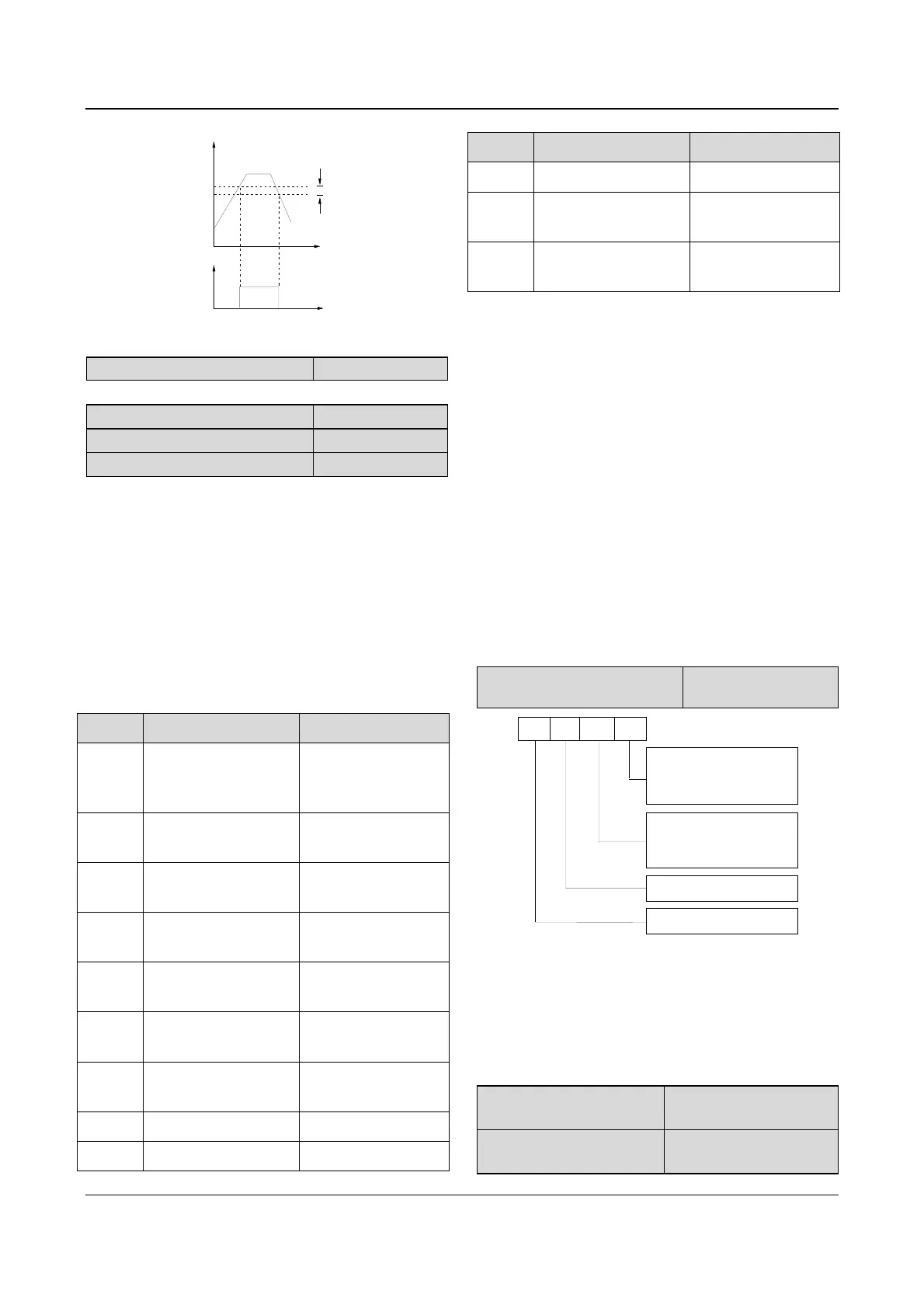
FDT1 lag
Time
Time
Y
FDT1 level
Output
frequency
Fig. 5-48 FDT level
F7.18~F7.25 Reserved
F7.26 Functions of terminal AO1
Range:0~11【0】
F7.27 Functions of terminal AO2
Range:0~11【3】
F7.28 Functions of terminal DO
Range:0~11【0】
AO1 and AO2 are analog output terminals, and DO is
pulse output terminals.
Refer to section 3.3.2 for the output characteristics of
AO1 and AO2, their analog output ranges are defined by
F7.29.
Pulse frequency range of DO: 0~Max output pulse
frequency (defined by F7.32).
The relationship between the displaying range and the
output values of AO1, AO2 and DO are given in Table
5-12.
Table 5-12 Displaying range of output terminals
Setting Functions Range
0
Output frequency
before slip
compensation
0~Max output
frequency
1
Output frequency after
slip compensation
0~Max output
frequency
2 Preset frequency
0~Max output
frequency
3 Output current
0~2 times of drive’s
rated current
4 Output current
0~2 times of motor’s
rated current
5 Output torque
0~2 times of motor’s
rated torque
6 Output voltage
0~1.2 times of drive’s
rated voltage
7 Bus voltage 0~800V
8 VCI 0~10V
Setting Functions Range
9 CCI 0~10V/0~20mA
10 Output power
0~2 times of rated
power
11
Extended function of
host 2
0~65535
If the extended function 2 of host 2 is enabled, the
output signal of terminal Y1, Y2 or TC is directly
controlled by a serial port. “65535” corresponds to the
Max output of 10V(or 20mA). Refer to the
communication protocol of EV2000 for details.
For example:
AO1 outputs 4~20mA, which indicates bus voltage
0~800V.
The settings:
①F7.26=7, output bus voltage;
②F7.29=01, output of terminal AO1 is 4~20mA;
③F7.30=100%, output gain is 100%;
④AO1 jumper of CN16 short circuited at 0/4-20mA side.
Note:
If terminal X8 selects functions of 44~46, DO is disabled
automatically
F7.29 Analog output range
selection
Range:00~11【00】
A
B
C
D
AO1 output range
0: 0~10V or 0~20mA
1: 2~10V or 4~20mA
Reserved
AO2 output range
0: 0~10V
or
0~20mA
1: 2~10V
or
4~20mA
Reserved
Fig. 5-49 analog output offset settings
Where,
A: thousand’s place B: Hundred’s place
C: Ten’s place D: Unit’s place
F7.29 is used to select analog output ranges of AO1 and
AO2.
F7.30 Output gain of AO1
Range:0.0~200.0%
【100.0%】
F7.31 Output gain of AO2
Range:0.0~200.0%
【100.0%】