68 Chapter 5 Parameter Introductions
EV2000 Series Universal Variable Speed Drive User Manual
As to the analog output of AO1 and AO2, you can adjust
the output gain to change the measuring range or
calibrate the meter.
Note:
Changing the settings of F7.30 and F7.31 will influence the
analog output.
F7.32 Maximum output
frequency of DO
Range:0~50.0kHz
【10.0KHz】
F7.32 defines the permissible maximum frequency of
DO, refer to F7.28.
F7.33 Preset counting value
Range: F7.34~9999【0】
F7.34 Specified counting value
Range: 0~F7.33【0】
F7.33 and F7.34 are complements for No. 12 and 13
functions in Table-5-11.
It defines after Xi receives the number of pulse F7.33,
the relay or Yi (bi-direction open-collector output
terminal) will give a signal.
For example: as shown in Fig. 5-50, when the eighth
pulse signal is received by terminal Xi, Y1 outputs an
indicating signal. At this time F7.33=8.
When Xi receives the number of pulse F7.34, Yi will give
a signal which will last until F7.33 arrives.
As shown in Fig. 5-50, when Xi receives the 5th pulse,
Y2 outputs an indication signal. It lasts until X1 receives
the 8th pulse. In this case, F7.34=5, F7.33=8. F7.34 is
invalid if it is bigger than F7.33.
1234567 89
Xi
input
Y
1
Y
2
Fig. 5-50 Preset and specified pulse number
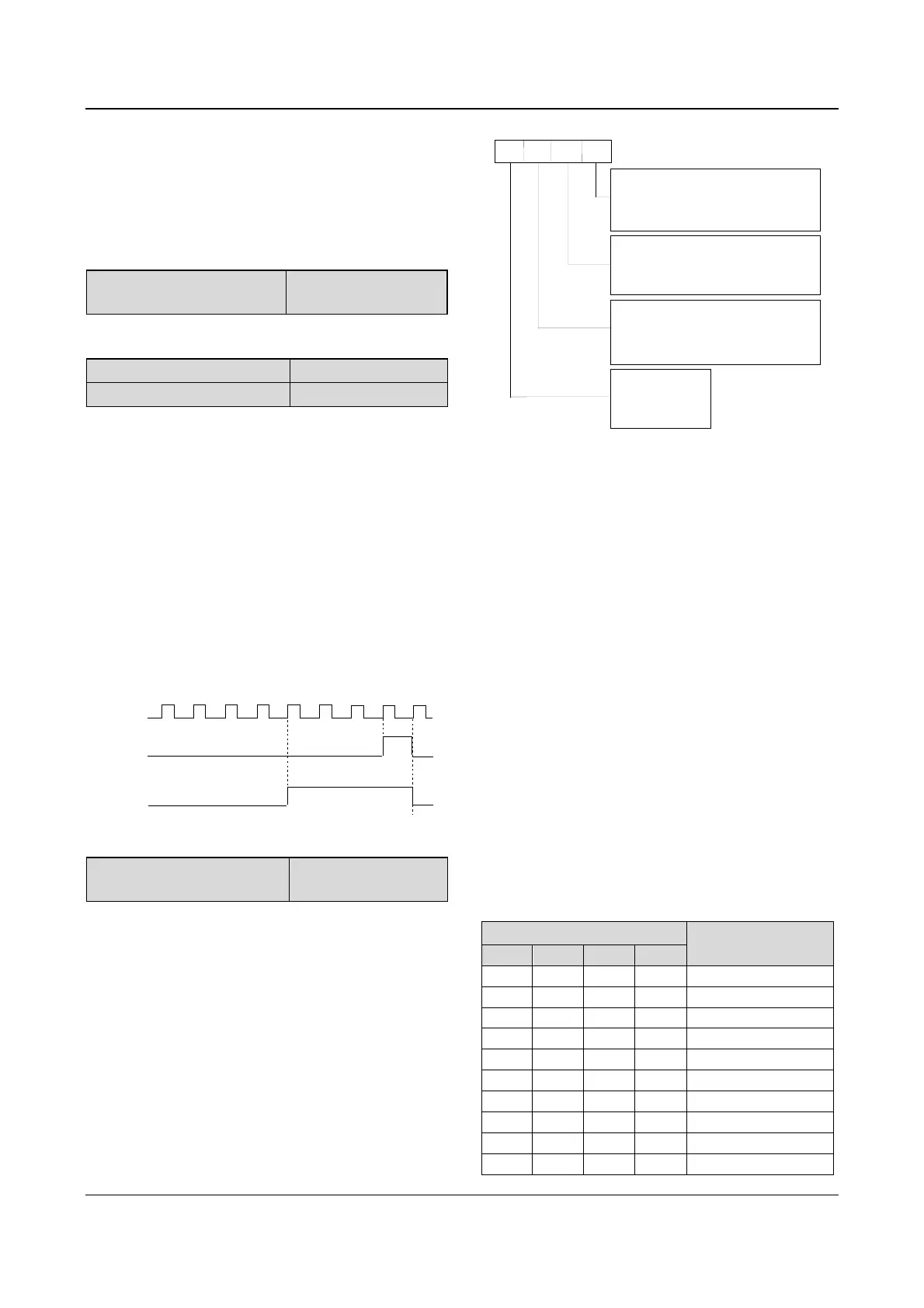
F7.35 Terminal’s positive and
negative logic
Range:000~FFFH
【000H】
A
B
C
D
BIT0 : positive/negative logic of
X1
BIT1 : positive/negative logic of
X2
BIT2 : positive/negative logic of X3
BIT3 : positive/negative logic of X4
BIT0 : positive/negative logic of X5
BIT1 : positive/negative logic of
X6
BIT2
: positive/negative logic of X7
BIT3:
positive/negative logic of
X8
BIT0
: positive/negative logic of
FWD
BIT1
: positive/negative logic of
REV
BIT2
: positive/negative logic of
Y1
BIT3
: positive/negative logic of
Y2
BIT0: reserved
BIT1: reserved
BIT2: reserved
BIT3: reserved
Fig. 5-51 terminal’s positive and negative logic
Where,
A: Thousand’s place B: Hundred’s place
C: Ten’s place D: Unit’s place
F7.35 defines the terminal’s positive and negative logic
Positive logic: Terminal Xi is enabled if it is connected to
the common terminal;
Negative logic: Terminal Xi is disabled if it is connected
to the common terminal;
If the bit is set at 0, it means positive logic; if set at 1, it
means negative logic.
For example:
If X1~X8 are required to be positive logic, terminals
FWD and REV are required to be negative logic,
terminal Y1 is positive logic and terminal Y2 is negative
logic, then the settings:
Logic status of X4~X1 is 0000, and the hex value is 0;
Logic status of X8~X5 is 0000, and the hex value is 0,;
Logic status of Y2, Y1, REV and FWD is 1011, and the
hex value is B, so F7.35 should be set at “0B00”. Refer
to Table 5-13.
Table 5-13 Conversion of binary code and hex value
Binary settings Hex value
(Displaying of LED)
Bit3 Bit2 Bit1 Bit0
0 0 0 0 0
0 0 0 1 1
0 0 1 0 2
0 0 1 1 3
0 1 0 0 4
0 1 0 1 5
0 1 1 0 6
0 1 1 1 7
1 0 0 0 8
1 0 0 1 9