Appendix 1 Parameters 93
EV2000 Series Universal Variable Speed Drive User Manual
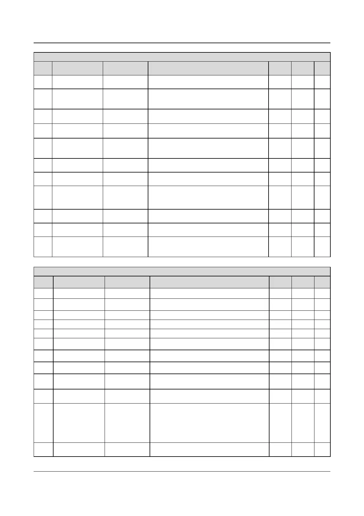
Group F2: Starting and Braking Parameters
Para. Name LCD Display Setting range Unit
Factory
setting
Modif.
F2.04
DC injection braking
time at start
BRAK TIME
0.0 (disabled), 0.1~30.0s
0.1s 0.0s
○
F2.05
Accelerating/deceleratin
g mode selection
ACC/DEC MODE
0:Linear Accelerating / decelerating mode
1:S curve
2:Auto Accelerating/decelerating
1 0
×
F2.06 Start section of S curve
S CURVE START
SEC
10.0%~50.0%(Acc/Dec time)
F2.06+F2.07≤90%
0.1% 20.0%
○
F2.07 Rising time of S curve S CURVE UP
10.0%~80.0%(Acc/Dec time)
F2.06+F2.07≤90%
0.1% 60.0%
○
F2.08 Stopping Mode STOP MODE
0: Dec to stop
1: Coast to stop
2: Dec to stop plus DC injection braking
1 0
×
F2.09
DC injection braking
initial frequency at stop
INI BRAK FREQ 0.00~60.00Hz 0.01Hz 0.00Hz
○
F2.10
DC injection braking
waiting time at stop
BRAK WAIT TIME 0.00~10.00s 0.01s 0.00s
○
F2.11
DC injection braking
current at stop
BRAK CURR AT
STOP
Depending on the type of the drive
P type: 0.0~80.0% of drive’s rated current
G type: 0.0~100.0% of drive’s rated current
0.1% 0.0%
○
F2.12
DC injection braking
time at stop
BRAK TIME AT
STOP
0.0 (disabled), 0.1~30.0s
0.1s 0.0s
○
F2.13 Dynamic braking BRAK UNIT SELE
0: Dynamic braking is not used
1: Dynamic braking is used
1 0
×
F2.14
Ratio of working time of
braking kit to drive’s
total working time
UTILITY OF BRAK
UNIT
0.0~100.0%
Note: valid for the built-in braking kit of 5.5/7.5kW drive
and dynamic braking should be applied in Dec process
0.1% 2.0%
×
Group F3: Auxiliary parameters
Para. Name
LCD Display Setting range Unit
Factory
setting
Modif.
F3.00 Run reverse disabled RUN REV DISABLE 0:Run reverse enabled 1:Run reverse disabled 1 0
×
F3.01
Run reverse/forward dead
time
FWD/REV DEAD TIME 0~3600s 0.1s 0.0s
○
F3.02 Reserved RESERVED - - 0 *
F3.03 Reserved RESERVED - - 0 *
F3.04 Reserved RESERVED - - 0 *
F3.05
Auto energy saving
operation
ENERGY-SAVING OPR 0:disabled 1:enabled 1 0
×
F3.06 AVR function AVR FUNC
0: disabled 1:enabled
2: disabled in decelerating process
1 2
×
F3.07 Gain of Slip compensation
SLIP COMPENSATION
GAIN
0.0%~300.0% 0.1% 100.0%
○
F3.08 Slip compensation limit
SLIP COMPENSATION
LIMIT
0.0%~250.0% 0.1% 200.0%
○
F3.09 Compensation time
COMPENSATION TIME
CONST
0.1~25.0s 0.1s 2.0s
×
F3.10
Carrier frequency
adjustment
CARRIER FREQ
Type G: 5.5kW~45kW
Type P: 7.5kW~55kW: 15k~3k
Type G: 55kW~90kW
Type P: 75kW~110kW: 10k~1k
Type G: 110kW~220kW
Type P: 132kW~280kW: 6k~0.7k
0.1kHz
8.0kHz
3.0kHz
2.0kHz
○
F3.11
Carrier frequency
auto-tuning
CARRIER FREQ
REGULATION SELE
0:disabled
1:Enabled
1 1
○
 Loading...


