Maintenance
March 2006
10-13
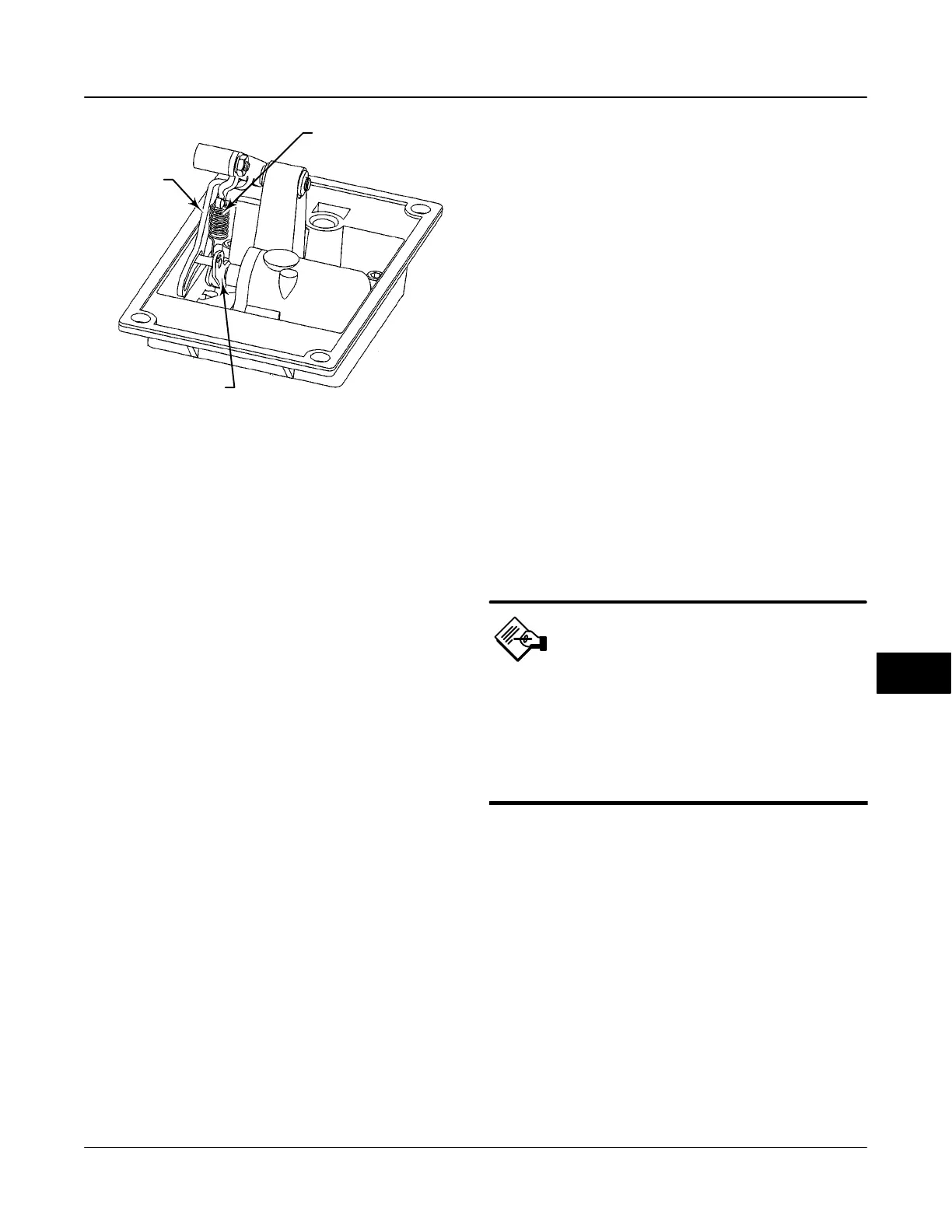
Figure 10-7. Type DVC6020f digital Valve Controller, bias
Spring (key 82) Installation
BIAS SPRING
(KEY 82)
ARM ASSEMBLY (KEY 91)
FEEDBACK
ARM
ASSEMBLY
(KEY 84)
E0734 / IL
NOTE:
INSTALL BIAS SPRING WITH SMALLER DIAMETER HOOK
CONNECTED TO ARM ASSEMBLY (KEY 91) AND WITH BOTH HOOK
OPENINGS TOWARD CENTER OF BRACKET.
10. While observing the resistance, tighten the screw
(key 80) to secure the feedback arm to the travel
sensor shaft. Be sure the resistance reading remains
at the calculated resistance determined in step 6,
$100 ohms. Paint the screw to discourage tampering
with the connection.
11. Disconnect the multimeter from the travel sensor
connector.
12. Apply lubricant (key 63 or equivalent) to the pin
portion of the arm assembly (key 91).
13. Position the mounting bracket over the back of the
digital valve controller. Push the feedback arm
assembly (key 84) toward the housing and engage
the pin of the arm assembly into the slot in the
feedback arm.
14. Install the mounting bracket (key 74).
15. Install the bias spring (key 82) as shown in
figure 10-7.
16. For the DVC6020f only, connect the travel sensor
connector to the PWB as described in Replacing the
Module Base.
17. Travel sensor replacement is complete. Install the
digital valve controller on the actuator.
Travel Sensor Adjustment with the Field
Communicator
The next two steps do not apply if you used a
multimeter to adjust the travel sensor. Perform these
steps only if you elected to adjust the travel sensor
using the Field Communicator.
18. For the DVC6020f only, connect the travel sensor
connector to the PWB as described in Replacing the
Module Base.
19. For both the DVC6020f and the DVC6025,
perform the appropriate Travel Sensor Adjust
procedure in the Calibration section.
Type DVC6030f Digital Valve Controller
and Type DVC6035 Remote Feedback Unit
Refer to figure 11-6 for Type DVC6030f and 11-7 for
Type DVC6035 key number locations.
1. Apply lubricant (key 63) to the travel sensor
assembly threads.
2. Screw the travel sensor assembly (key 223) into
the housing until it is tight.
If assembling a DVC6030f digital valve controller, use
step 3a. If assembling a DVC6035 remote feedback
unit, use step 3b.
3. a. Connect the travel sensor connector to the PWB
as described in the Replacing the Module Base
procedure.
b. Connect the three travel sensor wires to the
terminals.
Note
For the Type DVC6035 feedback unit,
connect the potentiometer assembly
(key 223) wires to the terminals as
follows:
red terminal 1
white terminal 2
black terminal 3.
4. Loosely assemble the bias spring (key 78), screw
(key 80), plain washer (key 163), and nut (key 81) to
the feedback arm (key 79), if not already installed.
5. Attach the feedback arm (key 79) to the travel
sensor shaft.
Two methods are available for adjusting the travel
sensor. You can use a multimeter to measure the
potentiometer resistance, or if you have a Field
Communicator, you can use the procedure in the
Calibration section. To use the multimeter, perform
steps 6 through 14. To use the Field Communicator,
skip to step 15.
Travel Sensor Adjustment with a Multimeter
6. Align the feedback arm (key 79) to the housing
(key 1) by inserting the alignment pin (key 46) through
10
 Loading...


