FloBoss 107 Instruction Manual
6-2 Sensors and Transducers Revised June-2017
Note: You set values for MVS transmitters using ROCLINK
800’s MVS Sensor screen (Configure > I/O > MVS
Sensor).
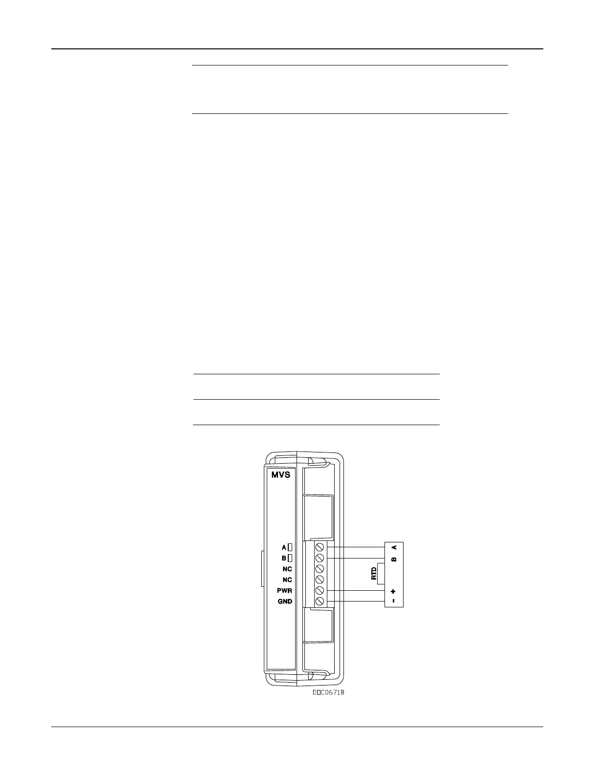
Once you set a unique address for each transmitter, connect the
transmitters in a multi-drop (or “daisy-chair”) configuration (see
Figure 6-2). The only requirement for multi-drop wiring is that
you tie all like terminals together. This means all the “A”
terminals on the devices are electrically connected to the FB107’s
“A” terminal and so on.
MVS modules have removable terminal blocks for convenient
wiring and servicing. The terminal blocks can accommodate size
16 to 24 AWG.
The FB107 scans each MVS transmitter once every second,
accessing values for differential pressure, static pressure, and
temperature as inputs for flow calculations, history, calibration,
and alarming.
Each input unit is based on selected system units:
 Loading...


