EasyManuals Logo

Emerson FloBoss 107 User Manual

Emerson FloBoss 107
152 pages
To Next Page IconTo Next Page
To Previous Page IconTo Previous Page
Page #75 background imageLoading...
Page #75 background image
FloBoss 107 Instruction Manual
Revised June-2017 Inputs and Outputs 4-17
SWITCHED
DEVICESUPPLY
POWER
LOW SIDE SWITCH
Figure 4-13. Discrete Output Wiring - Low Side Switch (on CPU Module)
SWITCHED
DEVICESUPPLY
POWER
HIGH SIDE SWITCH
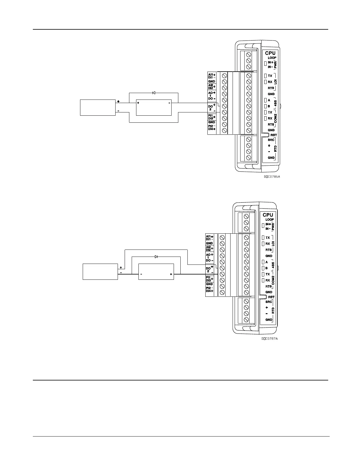
Figure 4-14. Discrete Output Wiring - High Side Switch (on CPU Module)
4.11 Discrete Outputs Relay (DOR) Module
The Discrete Output Relay (DOR) module provides control over various
discrete output field devices. An FB107 can support a maximum of six
DOR modules.
DOR modules provide six channels of discrete outputs that may be set to
send a control signal to a specified device. Refer to Figures 4-15 and 4-

Table of Contents

Other manuals for Emerson FloBoss 107

Questions and Answers:

Question and Answer IconNeed help?

Do you have a question about the Emerson FloBoss 107 and is the answer not in the manual?

Emerson FloBoss 107 Specifications

General IconGeneral
BrandEmerson
ModelFloBoss 107
CategoryController
LanguageEnglish

Related product manuals