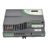
FloBoss 107 Instruction Manual
Revised June-2017 Inputs and Outputs 4-7
Note: Once you remove a module, always be sure to replace its cover.
This protects the module slot from dust and prevents damage to
the cover’s locking mechanism.
4.4 Wiring a Module
I/O wiring requirements are site and application dependent. Local, state,
or NEC requirements determine the I/O wiring installation methods.
Direct burial cable, conduit and cable, or overhead cables are options for
I/O wiring installations.
All I/O modules, the CPU I/O assembly, and RTD inputs have terminal
blocks for convenient wiring and servicing. The terminal blocks
accommodate size 16 to 24 AWG.
Failure to exercise proper electrostatic discharge precautions, such as
wearing a grounded wrist strap may reset the processor or damage
electronic components, resulting in interrupted operations.
To connect the wire to the removable block compression terminals:
1. Strip ¼ inch of insulation from the wire.
2. Insert the bare end into the clamp beneath the termination screw.
3. Tighten the screw, taking care not to over-torque it.
Expose a minimum of bare wire to prevent short circuits. Allow some
slack when making connections to prevent strain.
Note: Twisted-pair cable is recommended for I/O signal wiring.
4.5 Selecting the Type of I/O
Configure all AO/DO points in ROCLINK before connecting any wiring.
Failure to do so may result in physical damage to the I/O board.
Using ROCLINK 800, you select the type of input or output.
1. Log on to the FB107 using ROCLINK 800.
Note: ROCLINK 800 provides an enhanced graphical user interface
(GUI) for the FB107. This interface displays an image of the
FB107 above a tabbed screen (see Figures 4-4 and 4-5). You
select the FB107 module and then use the tabbed screen to
configure the components.
2. Click the I/O module. The display immediately under the FB107
image changes to reflect your selection.

 Loading...


