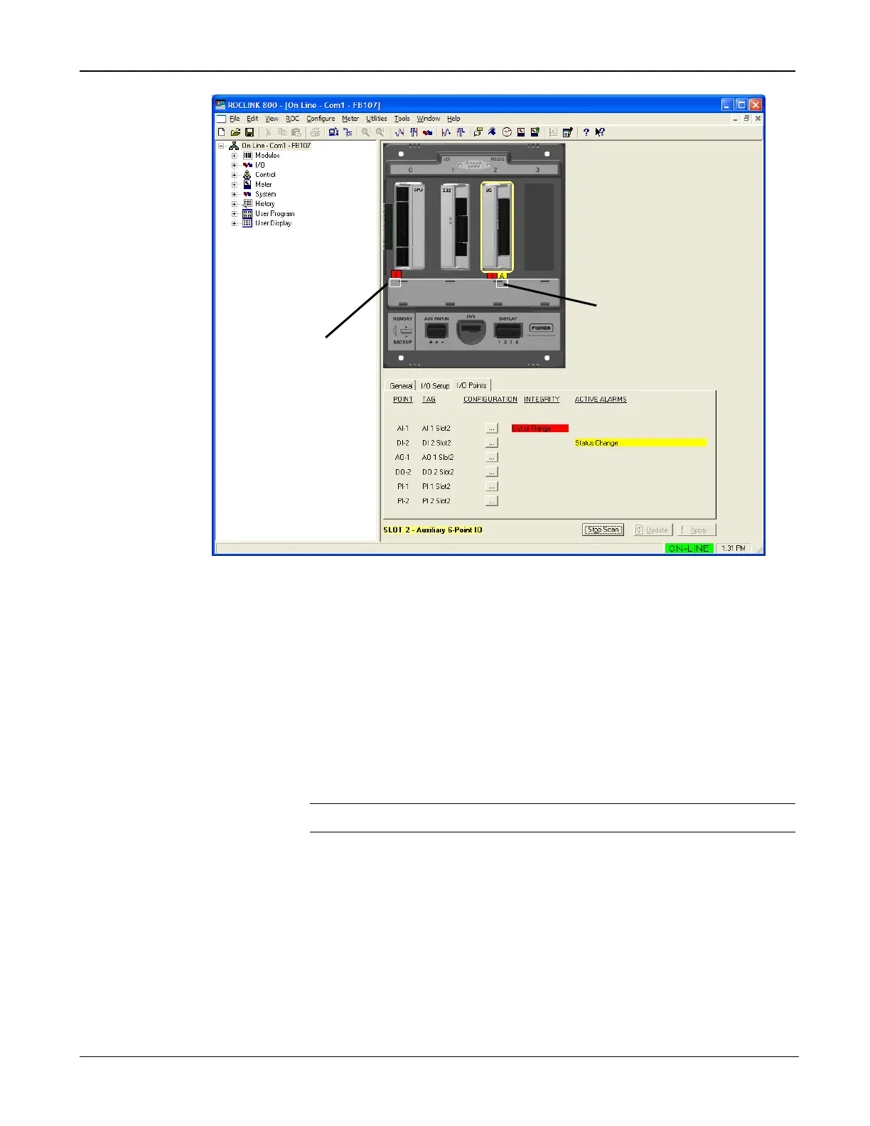
Figure 7-1. FB107 GUI
The I in a red box indicates an integrity alert. The A in a yellow box
indicates an alarm. This example screen shows a red integrity alert on the
CPU module’s I/O assembly, and both an integrity alert and an alarm on
the I/O module in slot 2. Note that the screen below the FB107 image
provides additional information on the alerts or alarms.
Situations that could cause integrity alerts include:
Communications failures: A module has failed or has been removed.
Note: This error occurs on I/O modules and MVS modules.
Module mismatch: The CPU expected to see one kind of module and
you actually installed another. Alternately, the installed module
(which is saved to the configuration file) does not match the module
physically installed in the FB107.
I/O points are out of range: For example, the AI point default A/D
counts are 643 to 3220. If the AI is open and the FB107 reads 0 A/D
counts, the FB107 generates an integrity alert.
Integrity alerts are typically related to hardware. Alarms are typically
related to user-defined configurations.

 Loading...


