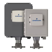
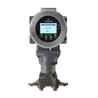
S600 Instruction Manual
P154 Prover Bit Links)..................................... 4-24
P154 Prover Board .......................................... 4-16
P188 HART Board........................................... 4-25
Page Reference Number................................... 5-5
Pages, data........................................................ 5-5
Power Supply..................................................... 3-3
Print .......................................................... 5-3, 5-12
Prover Board.................................................... 4-16
DIGIN........................................................... 4-18
DIGOUT....................................................... 4-20
Frequency Inputs......................................... 4-22
Jumpers....................................................... 4-24
PULSEIN ..................................................... 4-21
PULSEOUT ................................................. 4-22
PRT/RTD Inputs .............................................. 4-13
Pulse Inputs
Turbine ................................................. 4-9, 4-21
Pulse Outputs
PULSEOUT ........................................ 4-10, 4-22
R
Raw Pulse Output (RAWOUT) ........................ 4-11
Reflash Config File ............................................ 8-4
Reflash Firmware............................................... 8-4
Reflashing S600 ................................................ 8-7
Remote Display or PC ....................................... 3-7
RS-232............................................................... 3-5
RS-422 Port ....................................................... 3-6
RS-485 Port ....................................................... 3-6
RTD Inputs....................................................... 4-13
S
S600 .................................................................. 1-2
BIOS upgrade................................................ 8-8
Reflashing ..................................................... 8-7
Security Code .................................................... 5-8
Security Dump ................................................. 5-12
Send Config File ................................................ 8-4
Serial Port .......................................................... 3-5
SRAM ................................................................ 7-1
Clear .............................................................. 8-5
Start ................................................................... 7-1
Startup menu .............................................. 7-3, 8-2
Status/ID Line ............................................. 5-5, 5-7
T
Tables
2-1. Mounting Dimensions............................. 2-5
3-1. TB-1 Pin Connections ............................ 3-4
3-2. TB-1 Pin Connections ............................ 3-4
3-3. Battery Specifications............................. 3-5
3-4. Communication Ports............................. 3-5
3-5. COM3 and COM4 Pin Connections ....... 3-6
3-6. COM5, COM6, and COM7 Pin Connections
.................................................................... 3-7
3-7. COM1-2 Pin Connections ...................... 3-8
3-8. Device Connectors for the P152 CPU
Module......................................................... 3-9
3-9. CPU Bit Links ......................................... 3-9
4- 1. ANIN Pin Connections (SKT-A) ............ 4-5
4- 2. ANIN Pin Connections (SKT-B) ............ 4-5
4- 3. D/A Converter Output Pin Connections
(SKT-A)........................................................ 4-6
4- 4. DIGIN Pin Connections (SKT-B) ........... 4-7
4- 5. DIGIN Pin Connections (SKT-C)........... 4-7
4- 6. DIGOUT Pin Connections (SKT-B) ....... 4-8
4- 7. DIGOUT Pin Connections (SKT-C)....... 4-9
4- 8. Dual Pulse Input Pin Connection (SKT-C)
................................................................... 4-10
4- 9. PULSEOUT Pin Connections (SKT-B) 4-11
4-10. Raw Pulse Output Pin Connections (SKT-
C)............................................................... 4-12
4-11. Frequency Input Pin Connectors (SKT-B)
................................................................... 4-13
4-12. PRT/PRD Input Pin Connections (SKT-B)
................................................................... 4-14
4-13. P144 I/O Bit Links (Jumpers) ............. 4-15
4-14. Multiplex Mode Addressing ................ 4-16
4-15. DIGIN Pin Connectors (SKT-E).......... 4-19
4-16. DIGIN Pin Connections (SKT-F) ........ 4-20
4-17. DIGOUT Pin Connections (SKT-E).... 4-21
4-18. DIGOUT Pin Connections (SKT-F) .... 4-21
4-19. Dual Pulse Input Pin Connections (SKT-F)
................................................................... 4-22
4-20. PULSEOUT Pin Connections (SKT-E) .. 4-
22
4-21. Frequency Input Pin Connections (SKT-D)
................................................................... 4-23
4-22. Prover Bit Links (Jumpers)................. 4-24
4-23. Node Addressing - Communications Mode
Selection.................................................... 4-24
4-23. P188 HART Pin Connections (Socket B)4-
25
4-24. P188 HART Pin Connections (Socket A)4-
25
5-1. Front Panel Port Connections ................ 5-2
Troubleshooting ................................................. 8-1
Flash Failed ................................................... 8-4
Turbine Pulse Inputs.................................4-9, 4-21
U
Upgrading BIOS................................................. 8-8
V
View ................................................................... 5-4
VxWorks............................................................. 1-5
W
Warm Start......................................................... 7-1
Watchdog Relay................................................. 3-4
Webserver Interface .......................................... 6-4
Wiring................................................................. 3-1
Revised Jan-07 Index I-3

 Loading...


