Instruction Manual
748275-F
September 2003
Rosemount Analytical Inc. A Division of Emerson Process Management Description and Specifications 1-1
Model NGA2000 I/O Modules
SECTION 1
DESCRIPTION AND SPECIFICATIONS
1-1 OVERVIEW
NGA2000 components communicate with ex-
ternal devices through Input/Output (I/O)
Modules, printed circuit boards with two-way
communication potential.
Each of these I/O Modules is a self-contained
peer within the NGA2000 system. That is, it
has a microprocessor, memory, distinct func-
tionality and an identify addressable on the
network. Any I/O Module can be discon-
nected and replaced with the same or a new
I/O with no effect on the NGA2000 network.
In such an instance, all other components on
the network would remain functional.
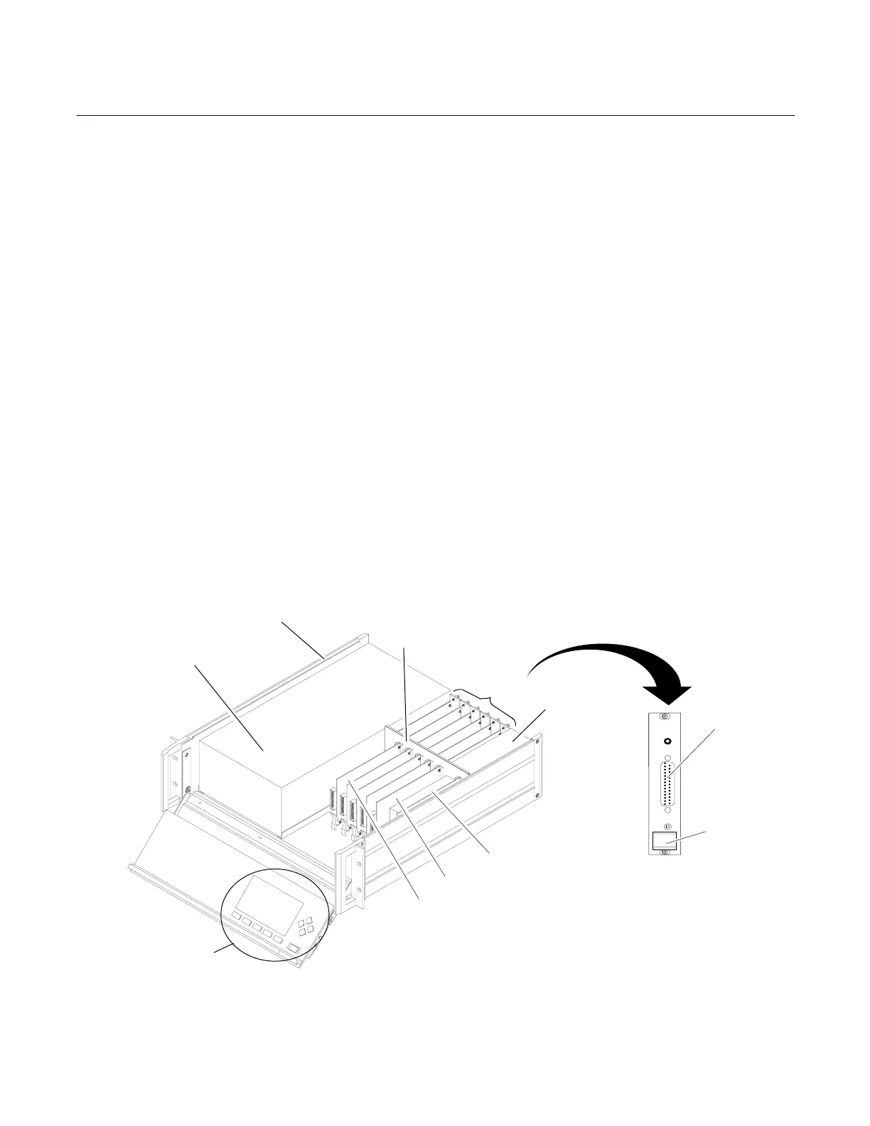
If a Platform is used in a particular application,
I/O Modules would be located in the rear left
of the Platform enclosure. See Figures 1-1
and 1-2.
Up to five I/O Modules can be installed in the
rear panel of the Platform. The sixth (far right)
slot is reserved for the Network I/O Port,
which can communicate with other NGA2000
components and any of several PC Interface
I/O Modules.
A variety of analog and digital I/O Modules
can communicate with chart recorders, distri-
bution control systems (DCS), data acquisition
systems (DAS) and other devices.
Among the available input and output func-
tions are voltage output (0 to 5 VDC), current
output (0 to 20 mA and 4 to 20 mA), alarms
(3), auto calibration, remote range change
and identification and gateway translations
(for example, HART protocol).
I/O back panel connections include 25-pin and
9-pin (RS-232) sub-D connectors. Sub-D to
standard analog terminal strip adapters are
available.
Figure 1-1. I/O Modules Location in Platform (Instrument Configuration)
I/O MODULE
Output
Connector
I/O Module
Extractor
I/O MODULE CONNECTION
(back View)
Power Input
Unit
Power Supply
Fan Board
Controller Board
Analyzer Module
Enclosure
Operator Interface
I/O Modules
Distribution
Assembly