Instruction Manual
748275-F
September 2003
Rosemount Analytical Inc. A Division of Emerson Process Management Description and Specifications 1-3
Model NGA2000 I/O Modules
5. Turn power on to all appropriate compo-
nents.
The network will initialize itself, thus recogniz-
ing and interacting with the new I/O Module.
To remove an I/O Module from the system,
follow powering guidelines in the first para-
graph of this section, unscrew and remove the
I/O Module, secure the I/O slot with a blank
panel and turn power on to all components.
1-4 SOFTWARE CONFIGURATION
See the following sections for instructions
about configuring the specific I/O Module(s) in
the user's system.
1-5 CONNECTIONS
See Figures 1-4 and 1-5 for pin assignments
for the backplane connector and the output
connector and adapter on all analog I/O Mod-
ules described in succeeding sections.
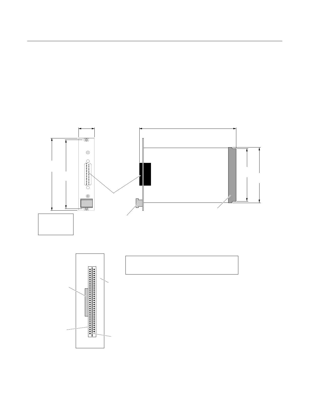
Figure 1-3. Analog I/O Module Component Location/Dimensions
Figure 1-4. Analog I/O Module Backplane Connector Pin Assignment
I/O MODULE
1.0
[25.4]
5.05
[128.3]
4.75
[120.7]
7.0
[177.8]
3.5
[88.9]
4.0
[101.6]
DIMENSIONS
INCH
[mm]
Backplane
Connector
Output
Connector
Module
Extractor
Orientation: PCB is located behind connector.
Pin Assignments
A1 +24 VDC
A2 +24 VDC Return
A7 Network
C1 +24 VDC
C2 +24 VDC Return
C7 Network
1
C
PCB
Rear of Plate
Output
Connector
Backplane
Connector