Instruction Manual
748275-F
September 2003
Rosemount Analytical Inc. A Division of Emerson Process Management System Auto Calibration I/O Module 4-3
Model NGA2000 I/O Modules
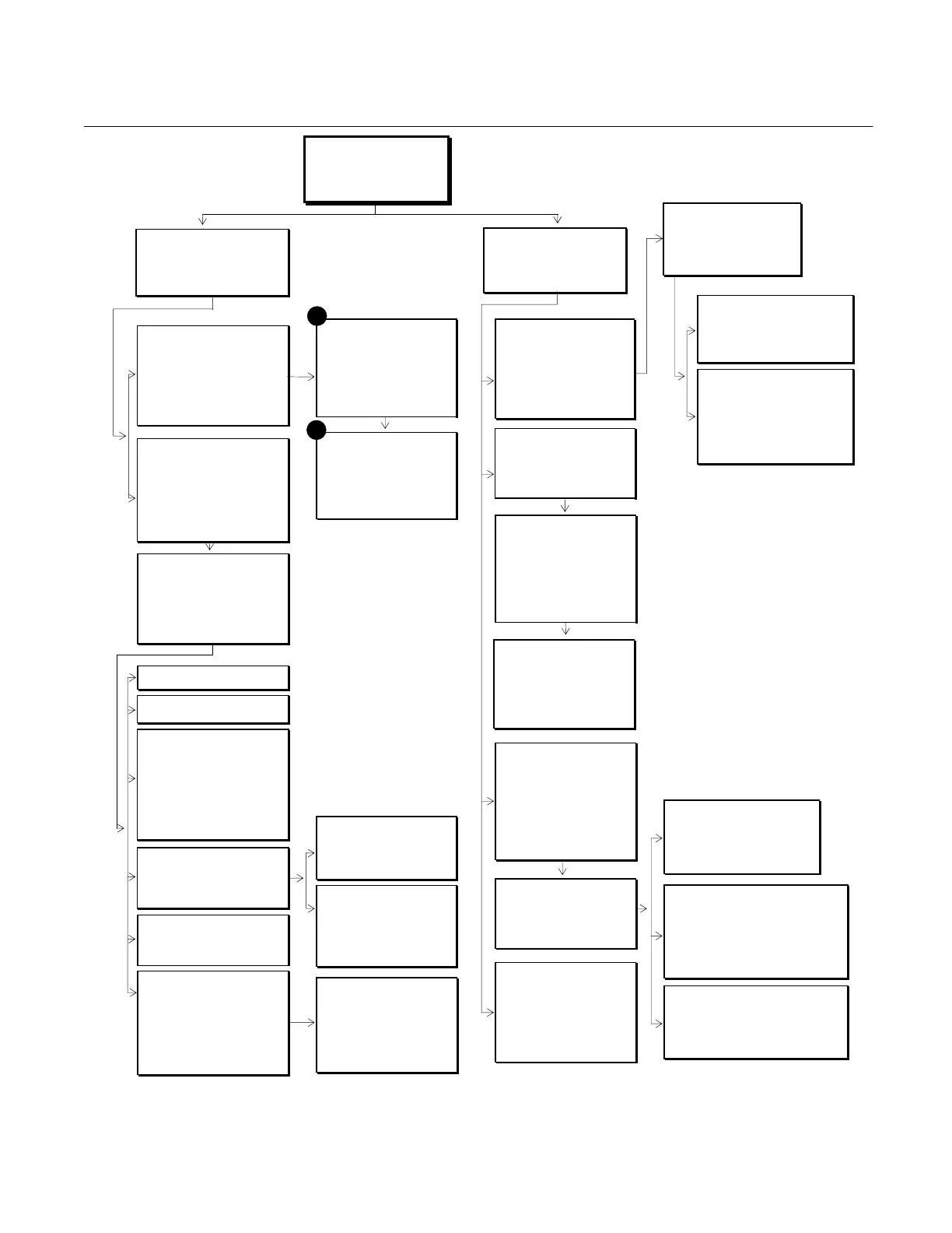
Figure 4-1. Software Displays Relative to System Auto Calibration I/O Module
Main Menu
Basic Controls...
Expert controls and setup...
(Operational Configuration)
Technical level configuration...
(Diagnostic and manufacturing/service)
Automatic calibration initiation
Gas selected: Sample
Calibration mode: Local
Analyzer status: Ready
Calibration cycle status: Sample
Analyzer 1 output: 110 ppm
Analyzer 2 output: 90 ppm
Analyzer 3 output: 100 ppm
Analyzer 4 output: 100 ppm
Manual calibration function...
System Set Up
Main display configuration...
Front panel control...
Date and time...
Miscellaneous control set up...
Module binding...
Interference binding...
System reset...
Record security codes...
System tag: Rosemount
Service Menus
Manufacturing data...
Service history...
Review stored data...
In maintenance since: N/A
Maintenance alert messages...
Record security codes...
Manufacturing data
Control module data...
Analyzer module data...
Module Tag
Module Tag
Module Tag
Module Tag
Module Tag
Module Tag
Module Tag
Module Tag
Diagnostic menus
Control module diagnostics...
Analyzer module diagnostics...
Module Tag
Module Tag
Module Tag
Module Tag
Module Tag
Module Tag
Module Tag
Module Tag
System Auto Cal Module
Power supplies...
Relay status...
Digital input lines...
Slot position: 1
IO module ID Auto 1043
System Auto Cal Module
Issue 1, 7-31-94
Software version: 2.1
Subnode base name: For:
Subnode 1 identification: For: 1
Subnode 2 identification: For: 2
Subnode 3 identification: For: 3
Subnode 4 identification: For: 4
System auto cal module ID: Auto 1043
Other module diagnostics
This screen reserved for other modules if
present:
Module Tag
Module Tag
Module Tag
Module Tag
Module Tag
Module Tag
Module Tag
Expert controls and setup
Expert analyzer controls...
Auxiliary module controls...
System set up...
Analyzer Module set up...
Auxiliary Module set up...
Manual calibration initiation
Gas selected: Sample
Calibration mode: Local
Span gas valve selected: 1
Analyzers affected: 1&2
Analyzer status: Ready
Calibration cycle status: Sample
Select appropriate gas, press START
Module Binding
Analyzer module selected: CLA 1023
Select modules...
Proposed bind:
View bindings...
Bind selections!
Unbind everything!
Modules Bound
Analyzer module selected: CLA 1023
Auxiliary module: Auto 1023
Auxiliary module: Acal 2322
Auxiliary module: HART 1092
Auxiliary module: None
Auxiliary module None
Auxiliary module: None
Proposed new bind:
Select IO modules
Select the modules you wish to bind to the
current analyzer.
Module Tag
Module Tag
Module Tag
Analog module power supplies
+15V analog is: 14.98 V
+15V analog was: 14.87 V
-15V analog is: -14.92 V
-15V analog was: -14.98 V
+5V digital is: 4.98 V
+5V digital was: 5.02 V
Relay status
Relay function: Auto
(Set this to TEST to set relays below)
Relay 1 status: On
Relay 1 measures: On
Relay 2 status: On
Relay 2 measures: On
Relay 3 status: On
Relay 3 measures: On
Input line status
Line 1 status: OFF
Line 2 status: OFF
Line 3 status: OFF
Line 4 status: OFF
Line 5 status: OFF
Line 6 status: OFF
#1
#2
Auxiliary module controls
This screen selects any module with a control
screen. This includes any auto calibration or
sample module bound to the analyzer.
Module Tag
Module Tag
Module Tag
Module Tag
Module Tag
Auxiliary module set up
Select an auxiliary module for set up
Module Tag
Module Tag
Module Tag
Module Tag
Module Tag
Module Tag
Module Tag
Module Tag
System Auto Cal Module
Automatic calibration initiation...
Manual calibration initiation...
Timing parameters...
Valve control parameters...
General parameters...
Number of zeros before the next span: 0
Analyzer identification...
Slot position 1
Automatic Calibration Initiation
See #1 above.
Manual Calibration Initiation
See #2above.
Timing parameters
Start sequence at this time-Day of month: 4
Start sequence at this time - Hrs: 4
Start sequence time - mins: 0
Calibration cycle period: 12 hrs
Local zero gas dwell time: 2 min
Local span gas dwell time: 2 min
Local sample dwell time: 1 min
Remote zero gas dwell time: 2 min
Remote span gas dwell time: 3 min
Remote sample dwell time: 1 min
Valve control parameters
Zero gas valve...
Span valve 1...
Span valve 2...
Span valve 3...
Span valve 4...
General parameters
Timed function: Cal
Zero checks per span checks: 4
Input line control: Enabled
This modules control status: Master
Analyzer identification
Analyzer 1 tag: CO
Analyzer 2 tag: CO
Analyzer 3 tag: CO
Analyzer 4 tag: CO
Analyzer 1 range: 2
Analyzer 2 range: 1
Analyzer 3 range: 3
Analyzer 4 range: 3
(Set up ranges in the analyzer menus)
Zero gas valve
Analyzers affected: All
Operation performed: Zero
Current status: Ready
Operates on ranges as selected in the
analyzer.
Span gas valve 1 (2,3,4)
Analyzers affected: 1&2
Operation performed: Zero
Current status: Ready
Analyzer 1 range: 1
Analyzer 2 range: 1
Analyzer 3 range: 1
Analyzer 4 range: 1
Range List
Range 1 lower limit: 0 ppm
Range 1 upper limit: 10 ppm
Range 2 lower limit: 0 ppm
Range 2 upper limit: 100 ppm
Range 3 lower limit: 0 ppm
Range 3 upper limit: 250 ppm
Range 4 lower limit: 0 ppm
Range 4 upper limit: 1000 ppm
Technical configuration menu
System set up...
Service menus...
Diagnostic menus...
Other module diagnostic menus...
Listing of all modules...