Instruction Manual Section 9: Alarm Relay Functions
LIQ-MAN-56 April 2017
Alarm Relay Functions 69
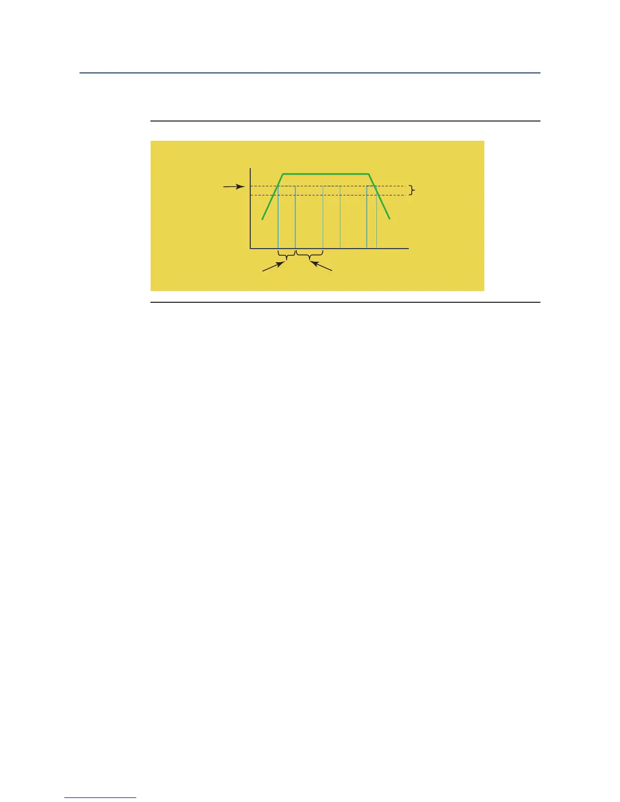
A schematic of the Delay Timer operation is shown:
9.3.2 Setup
Access Delay Timer by pressing ENTER/MENU from the main screen and then Program/Relays/
Configure Relay. From the main relay programming screen, program this feature as follows:
1. Relay: Assign a relay by highlighting the desired relay 1-4 and press ENTER/MENU.
2. Type: Select Delay Timer as the relay type and press ENTER/MENU.
3. Assign: Assign S1 (sensor 1), S2 (sensor 2 if available) or other available parameters to
the designated relay and press ENTER/MENU.
4. Logic: Set High for high reading setpoint logic or Low relay logic for low reading setpoint
logic and press ENTER/MENU.
5. Setpoint: Enter the desired setpoints value. This will activate an alarm event when the
process measurement reaches the entered setpoint value. Press ENTER/MENU. See
Table 9-2 for entry limits.
6. Deadband: To set deadband as a measurement value, enter the change in the process
value needed after the relay deactivates to return to normal (and thereby preventing re-
peated alarm activation). Press ENTER/MENU.
7. Select NEXT Press ENTER/MENU to advance to the next setup screen.
8. On time: Enter the time in minutes (X.X min) for the relay to remain energized. The as-
signed measurement value will be on hold during this time.
9. Delay time: Enter the time in minutes (X.X min) to take the assigned measurement off
hold after the relay is re-energized to begin reporting live values.
10. Normal state: Set the normal alarm condition as Open or Closed and press
ENTER/MENU. Program the normal state to define the desired alarm default state to nor-
mally open or normally closed upon power up.
Figure 9-2. Delay Timer Alarm operation
 Loading...


