Safety
Information
Introduction
Product
information
System
design
Mechanical
installation
Electrical
installation
Getting
started
Optimisation
Parameters
Technical
data
Component
sizing
Diagnostics
142 Unidrive SP Regen Installation Guide
www.controltechniques.com Issue Number: 2
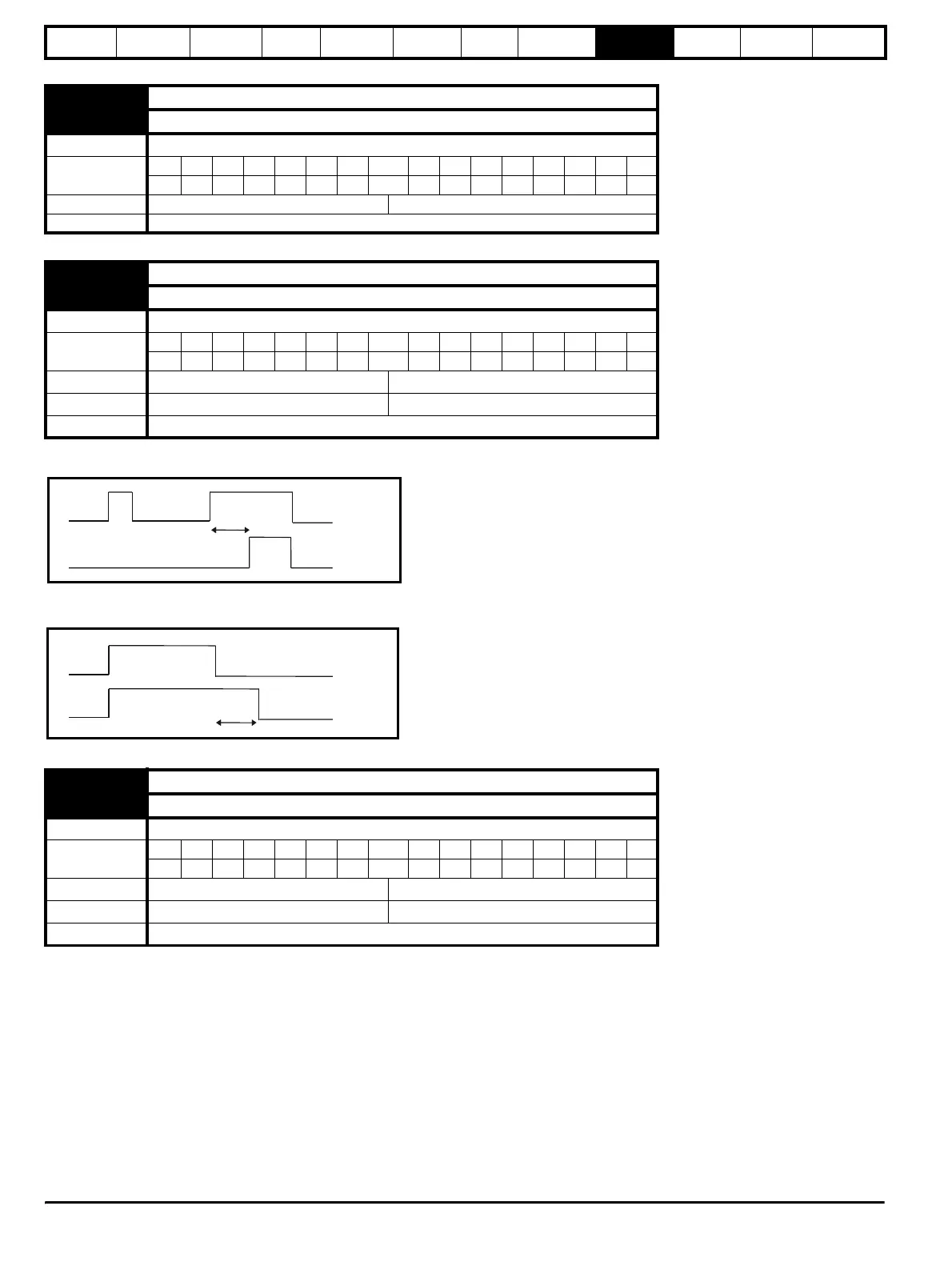
If the delay parameter is positive, the delay ensures that the output does not become active until an active condition has been present at the input for
the delay time as shown below.
If the delay parameter is negative, the delay holds the output active for the delay period after the active condition has been removed as shown below.
Therefore an active input that lasts for 4ms or more will produce an output that lasts at least as long as the delay time.
9.08 Logic function 1 output invert
9.18 Logic function 2 output invert
Drive mode Regen
Coding
Bit SP FI DE Txt VM DP ND RA NC NV PT US RW BU PS
111
Default Regen 0
Update rate 4ms x number of menu 9 or 12 functions active
9.09 Logic function 1 delay
9.19 Logic function 2 delay
Drive mode Regen
Coding
Bit SP FI DE Txt VM DP ND RA NC NV PT US RW BU PS
111
Range Regen ±25.0 s
Default Regen 0.0
Update rate 4ms x number of menu 9 or 12 functions active
9.10 Logic function 1 destination
9.20 Logic function 2 destination
Drive mode Regen
Coding
Bit SP FI DE Txt VM DP ND RA NC NV PT US RW BU PS
1 2 1111
Range Regen Pr 0.00 to Pr 21.51
Default Regen Pr 0.00
Update rate Background
Delay
Input
Output
Delay
Input
Output