Safety
Information
Introduction
Product
information
System
design
Mechanical
installation
Electrical
installation
Getting
started
Optimisation
Parameters
Technical
data
Component
sizing
Diagnostics
118 Unidrive SP Regen Installation Guide
www.controltechniques.com Issue Number: 2
This parameter defines the nominal supply voltage when operating in low voltage mode. The actual value of the parameter is not used directly by the
drive, but is used to define the braking IGBT switching threshold and the over voltage trip level for low voltage mode (see Pr 6.44).
When power modules are connected in parallel various trips can be initiated from the power modules themselves. To aid identification of the source of
the trip the module number of the source can be stored in the module number and trip time log (Pr 10.41 to Pr 10.51). If the drive is a single module
drive the module number that is stored is normally zero. However, a UNISP6xxx or UNISP7xxx drive can be fitted with the interface circuits normally
intended for parallel operation, but it is a single module drive. In this case a module number of 1 is stored.
If Pr 6.49 is zero the module number is stored in the module number and trip time log. If this parameter is one, either the powered-up clock or run time
clock is stored in the module number and trip time log as defined by Pr 6.28. It should be noted that changing this parameter clears the trip, and
module number and trip time logs.
The drive comms system 128 bytes buffer used with ANSI or Modbus rtu protocols via the 485 connector can be controlled by a Solutions Module
under certain circumstances. This parameter shows which node has control of the buffer (0 (drv) = drive, 1 (Slot1) = Solutions Module in slot 1, etc. If
a Solutions Module has control of the buffer the drive will use an alternative buffer for 485 comms and the following restrictions will apply:
1. Comms messages via the 485 port are limited to a maximum of 32 bytes
2. The 6 pin keypad port will operate correctly with an LED keypad, but it will no longer operate with an LCD keypad
3. Modbus messages using the CMP protocol can only route messages to nodes within the drive. It will not be possible for these to be routed further,
i.e. via CT Net on an SM-Applications module.
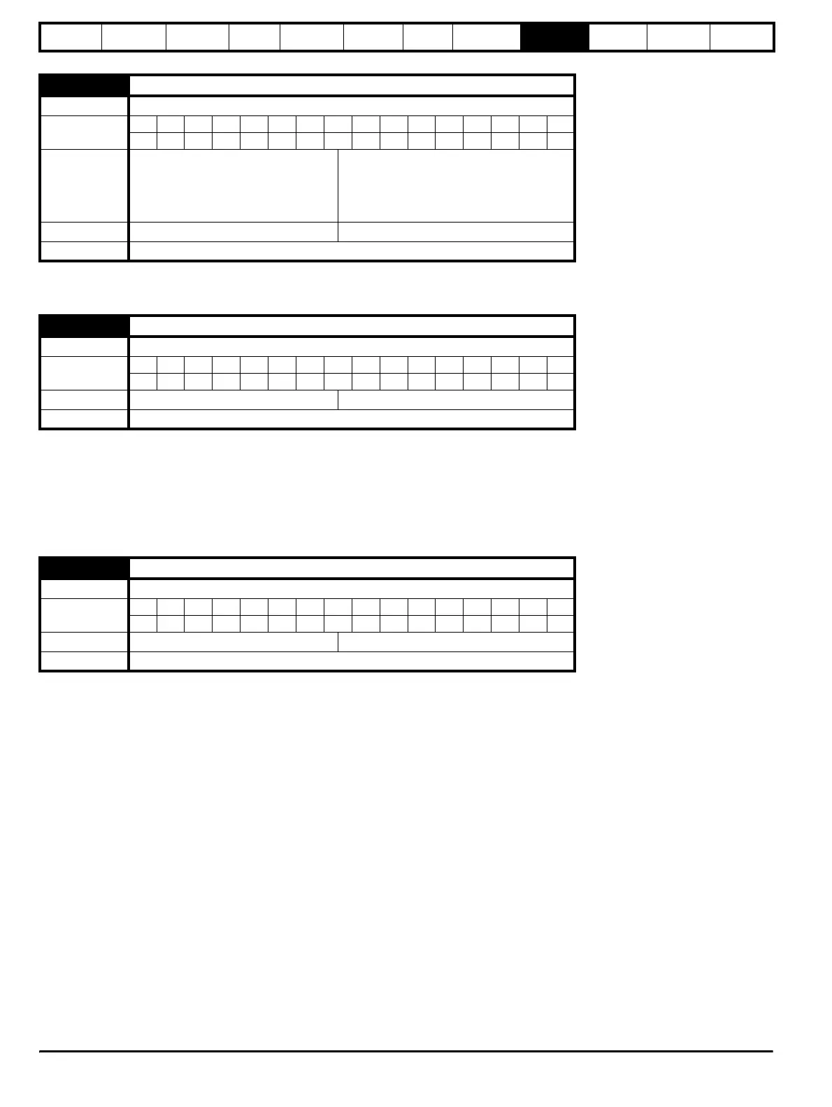
6.46 Nominal low voltage supply
Drive mode Regen
Coding
Bit SP FI DE Txt VM DP ND RA NC NV PT US RW BU PS
1111
Range Regen
48 - 48 - SP1 drives
48 - 72 - SP2, SP3 drives
48 - 72 - For all other 200V drives
48 - 96 - For all other 400V, 575V and 690V
drives
Default Regen 48
Update rate Background
6.49 Disable multi-module drive module number storing on trip
Drive mode Regen
Coding
Bit SP FI DE Txt VM DP ND RA NC NV PT US RW BU PS
111
Default Regen 0 (OFF)
Update rate Background
6.50 Drive comms state
Drive mode Regen
Coding
Bit SP FI DE Txt VM DP ND RA NC NV PT US RW BU PS
11111
Range Regen 0 to 3
Update rate Background