Safety
Information
Introduction
Product
information
System
design
Mechanical
installation
Electrical
installation
Getting
started
Optimisation Parameters
Technical
data
Component
sizing
Diagnostics
Unidrive SP Regen Installation Guide 215
Issue Number: 2 www.controltechniques.com
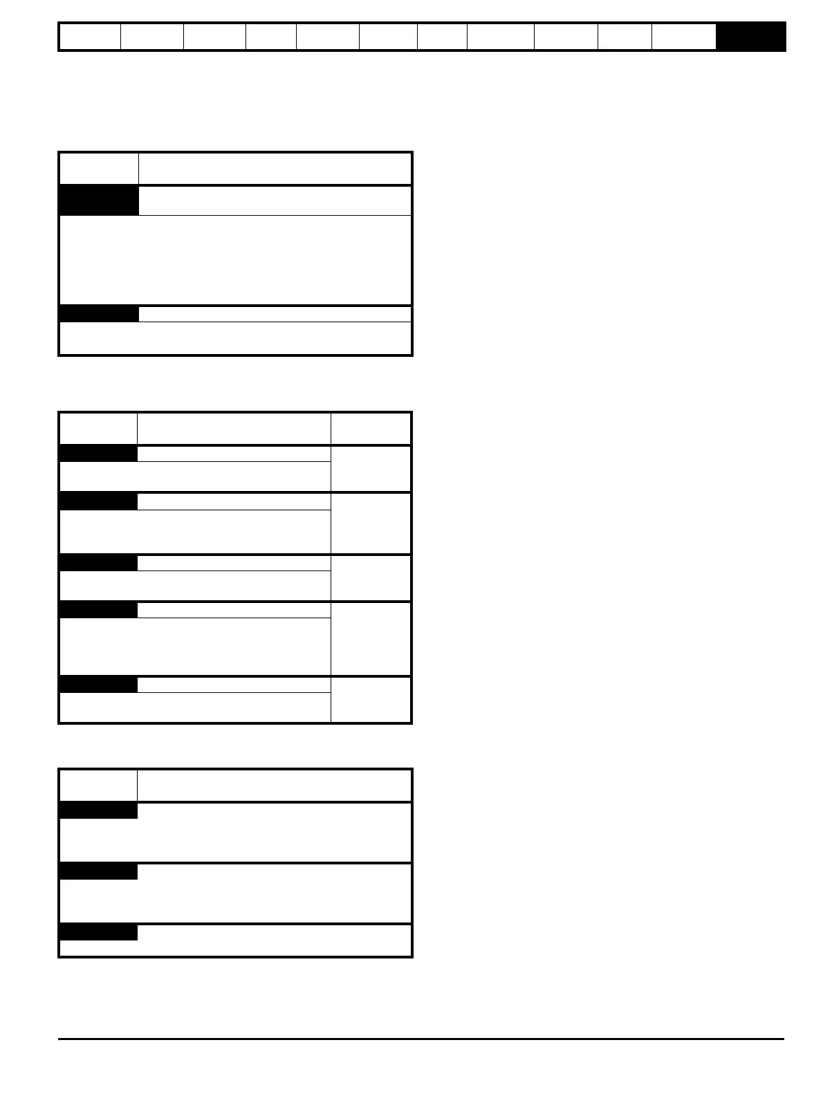
12.2 Alarm indications
In any mode an alarm flashes alternately with the data displayed on the
2
nd
row when one of the following conditions occur. If action is not taken
to eliminate any alarm except "Autotune" the drive may eventually trip.
Table 12-6 Alarm indications
12.3 Status indications
Table 12-7 Status indications
Table 12-8 Solutions Module and SMARTCARD status indications
at power-up
12.4 Displaying the trip history
The drive retains a log of the last 10 trips that have occurred in Pr 10.20
to Pr 10.29 and the corresponding time for each trip in Pr 10.43 to
Pr 10.51. The time of the trip is recorded from the powered-up clock (if
Pr 6.28 = 0) or from the run time clock (if Pr 6.28 = 1).
Pr 10.20 is the most recent trip, or the current trip if the drive is in a trip
condition (with the time of the trip stored in Pr 10.43). Pr 10.29 is the
oldest trip (with the time of the trip stored in Pr 10.51). Each time a new
trip occurs, all the parameters move down one, such that the current trip
(and time) is stored in Pr 10.20 (and Pr 10.43) and the oldest trip (and
time) is lost out of the bottom of the log.
If any parameter between Pr 10.20 and Pr 10.29 inclusive is read by
serial communications, then the trip number in Table 12-2 General trip
indications on page 207 is the value transmitted.
Lower
display
Description
Hot
Heatsink or control board or inverter IGBT over
temperature alarms are active
• The drive heatsink temperature has reached a threshold and the
drive will trip ‘Oh2’ if the temperature continues to rise (see the
‘Oh2’ trip).
Or
• The ambient temperature around the control PCB is approaching
the over temperature threshold (see the ‘O.CtL’ trip).
OVLd Motor overload
The motor I
2
t accumulator in the drive has reached 75% of the value at
which the drive will be tripped and the load on the drive is >100%
Upper
display
Description
Drive output
stage
ACt Regeneration mode active
Enabled
The Regen drive is enabled and synchronised to the
supply.
inh
Inhibit
Disabled
The drive is inhibited and cannot be run.
The drive enable signal is not applied to terminal 31 or
Pr 6.15 is set to 0.
PLC Onboard PLC program is running
Not applicable
An Onboard PLC program is fitted and running.
The lower display will flash ‘PLC’ once every 10s.
SCAn Scanning
Enabled
OL> The drive is searching for the motor frequency
when synchronising to a spinning motor.
Regen> The drive is enabled and is synchronising to
the line.
triP Trip condition
Disabled
The drive has tripped and is no longer controlling the
motor. The trip code appears on the lower display.
Lower
display
Description
boot
A parameter set is being transferred from the SMARTCARD to the
drive during power-up. For further information, refer to the Unidrive SP
User Guide.
cArd
The drive is writing a parameter set to the SMARTCARD during power-
up.
For further information, refer to the Unidrive SP User Guide.
loAding
The drive is writing information to a Solutions Module.