Safety
Information
Introduction
Product
information
System
design
Mechanical
installation
Electrical
installation
Getting
started
Optimisation Parameters
Technical
data
Component
sizing
Diagnostics
38 Unidrive SP Regen Installation Guide
www.controltechniques.com Issue Number: 2
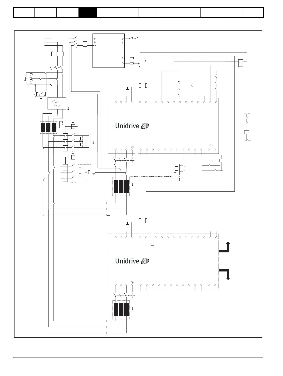
4.2.4 Multiple Regen, multiple motoring using Unidrive SPMC
Figure 4-4 Power connections: Multiple Regen, multiple motoring system
UVW
L1 L2 L3 PE
-DC +DC
-DC
+DC
21
1
2 3 4 5 6 7 8 9 10 11 41 42
22 23 24 25 26 27 28 29 30 31
K2
RFI
F1 F2 F3
Tc.1
L1
L2
L3
AC Supply
Connections
Motoring
drive DC
Connections
+24 output
Enable motor drive
Contactor closed
0 common
Drive enable
Rly.1
optional
Regen drive 1 master
S1
Unidrive
SPMC
L1
85
84
+DC
-DC
F16
F15
+24Vdc external supply
0V common
Regen inductor
thermistor
0V common
V
Aux.2
V
Aux.1
K2
AC Supply
Connections not used
Aux.3
L2
L3
F11
F10
F12
K3
L2
F14
F13
S6
Drive healthy
Reset input
UVW
L1 L2 L3 PE
-DC +DC
21
1
2 3 4 5 6 7 8 9 10 11 41 42
22 23 24 25 26 27 28 29 30 31
AC Supply
Connections
Motoring
drive DC
Connections
Regen drive 2 Slave
F18
F17
K4
AC Supply
Connections not used
L3
T.24
T.30
+10V user output
F5
F4
F6
F8
F7
F9
Aux.3
Aux.2a
Aux.2c
Aux.4c
4a 4b 4c Aux
Control cable
to regen master
Control cable
to additional
regen slave
K3
Aux.4b
Aux.2b
Vsupply
4a 4b 4c Aux
2a 2b 2c Aux
Aux.4a
L1
OPD1
Aux.1
OPD2
Aux.2
C2
C1
K1
L1 L2 L3
VDR1
VDR2
VDR3
VDR4
VDR5
VDR6
Contactor
control
Vsupply
K4