Equipment Features
The Controls and Indications section details the various features of the Radio Hub, Radio Cluster
Communicator and wireless devices.
Radio Hub
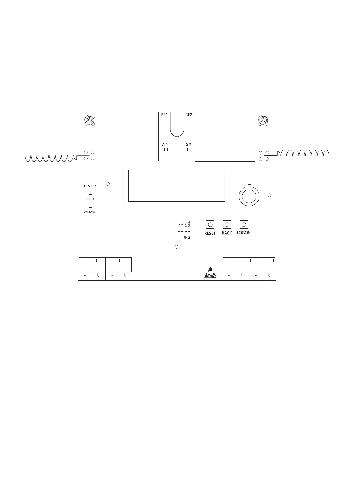
The Radio Hub has 3 visible LED indicators from the front of the housing and also internal LED indicators,
controls, display and connectors. This section explains their functionality.
External Indications
Power LED; a green LED will be visible on the front plate of the Radio Hub. This will be illuminated
constantly whilst power is supplied to the Radio Hub from the control panel, via the Loop 1 connection.
Fault LED; a yellow LED will be visible on the front plate of the Radio Hub. This will illuminate constantly
in the event of an aerial tamper fault on the Radio Hub.
System Fault LED; a yellow LED will ash if a checksum error is detected, in either the software program
or conguration data.
Page 11 of 40©2019 EMS Ltd. All rights reserved. MK98 Iss17 05/04/2019 AJM
LOOP 1 LOOP 2 LOOP 3 LOOP 4
+
-
+
-
+
-
+
-
+
-
+
-
+
-
+
-