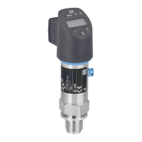
Wiring Ceraphant T PTC31, PTP31, PTP35
10 Endress+Hauser
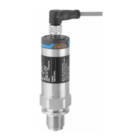
4.3 DC voltage version with cable
P01-PTx3xxxx-04-xx-xx-xx-004
Fig. 5: Ceraphant T with cable connection
C1: 1x PNP switch output
C2: PNP switch outputs R1 and m(R2)
C2’: PNP switch outputs R1 and m (diagnosis/break contact with adjustment "DESINA")
C3: PNP switch output with additional analog output (active)
C3’: PNP switch output with additional analog output (active) (assignment with "DESINA" setting)
Cable specification: all three versions 5-core, 4 x 0.2 mm
2
(25 AWG), PE 0.75 mm
2
(18 AWG)
–Core colours: BN = brown, BK = black, WH = white, BU = blue, GNYE = green/yellow
"
Caution!
To avoid the analog input damaging of a PLC, do not connect the active PNP switch output of
the device to the 4...20 mA input of a PLC.
4.4 Supply voltage
DC voltage version
12...30 V DC
4.5 Current consumption
Without load < 60 mA, with reverse polarity protection
4.6 Post-connection check
Perform the following checks after completing electrical installation of the device:
• Does the supply voltage match the specifications on the nameplate?
• Is the device connected as per Chap. 4.1/ Chap. 4.2/ Chap. 4.3?
• Are all screws firmly tightened?
As soon as voltage is applied to the device, the connected on-site display lights up.
L–
L–
L–
L–
L+
L+
L+
L+
R1
R1
Diag.
4...20mA
4...20mA
R1
➀
WH
WH
WH
BU
GNYE
GNYE
GNYE
GNYE
BU
BU
BU
BN
BN
BN
BN
BK
BK
BK
BK
C1
C2
C2’
C3
C3’

 Loading...


