Deltabar FMD72 Electrical connection
Endress+Hauser 17
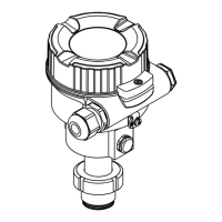
• Screw on the housing cover of the terminal compartment of the sensor module HP.
• Guide the cable of the transmitter through the cable gland of the sensor module HP. Use the
shielded 4-wire cable that is provided. The wire ends are color-coded to match the
corresponding terminal.
• Connect device in accordance with the following diagram.
• Screw down housing cover.
6
5
5
7
2 3 4
3
4
1
21
6
5
NPT ½"
M20
8
8
A0017529
1
BK (black)
2 BU (blue)
3 WH (white)
4 BN (brown)
5 Sensor module HP
6 Transmitter
7 Ground terminal
8 Torque 0.4 Nm
7.2.1 Screening with cable shield
Screening with cable shield is described in the associated documentation SD00354P. The
documentation is provided with the connecting cables.

 Loading...