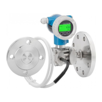
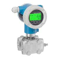
Electrical connection Deltabar FMD72
20 Endress+Hauser
7.4 Connection conditions
7.4.1 Cable specification for transmitter connection
See Operating Instructions BA01044P on the CD-ROM supplied.
7.4.2 Cable glands
See Operating Instructions BA01044P on the CD-ROM supplied.
7.4.3 Overvoltage protection (optional)
See Operating Instructions BA01044P on the CD-ROM supplied.
7.5 Connection data
7.5.1 Maximum load
See Operating Instructions BA01044P on the CD-ROM supplied.
7.5.2 Shielding
• You achieve optimum shielding against disturbances if the shielding is connected on both sides
(in the cabinet and on the device). If potential equalization currents are expected in the plant,
only ground shielding on one side, preferably at the transmitter.
• When using in hazardous areas, you must observe the applicable regulations. Separate Ex
documentation with additional technical data and instructions is included with all Ex systems
as standard.
7.6 Post-connection check
m
Is the device or cable undamaged (visual check)?
m Do the cables comply with the requirements ?
m Do the cables have adequate strain relief?
m Are all the cable glands installed, firmly tightened and leak-tight?
m Does the supply voltage match the specifications on the nameplate?
m Is the terminal assignment correct ?
m If required: Has protective ground connection been established ?
m If supply voltage is present, is the device ready for operation and do values appear on the display module?
m Are all housing covers installed and firmly tightened?
m Is the securing clamp tightened correctly?

 Loading...