6/16
Endress+Hauser
Kits CM42
5. Austausch von Eingangsmodulen
• Öffnen Sie den Deckel (siehe Kapitel 4).
• Die schwarzen Klemmleisten auf den Modu-
len sind abziehbar. Solange identische Mo-
dule getauscht werden, brauchen Sie keine
Leitungen abzuklemmen.
• Unterbrechen Sie die Geräteversorgung,
z. B. indem Sie am CPU-Modul die Klemm-
leiste mit Klemmen 133+134 bzw. mit
Klemmen 997+998 abziehen).
• Entfernen Sie das Eingangsmodul:
- Ziehen Sie die Klemmleiste des Eingangs-
moduls (schmales Modul rechts) ab.
- Ziehen Sie die beiden schwarzen Laschen
nach oben um das Modul zu entriegeln.
- Ziehen Sie das Modul an den Laschen heraus.
• Bauen Sie das neue Eingangsmodul ein:
- Führen Sie das neues Modul in die Nuten
des linken Moduls ein und schieben Sie
es dann bis zum Anschlag ein.
- Drücken Sie beide Laschen nach unten.
Dadurch wird das Modul in der Hutschiene
rüttelsicher fixiert.
- Stecken Sie dann die Klemmleiste des
Eingangsmoduls wieder auf.
• Stellen Sie die Geräteversorgung wieder
her (z. B. Klemmleisten 133+134 bzw.
997+998 wieder aufstecken).
• Prüfen Sie die Funktion des Gerätes.
• Nach Tausch eines digitalen Eingangsmoduls
(FSDG1) ist keine Kalibrierung notwendig.
• Nach Tausch eines analogen Eingangsmoduls
(FSPH1, FSLI1, FSLC1) ist eine erneute
Sensorkalibrierung erforderlich.
5. Exchange of input modules
• Open the lid (see chapter 4).
• The black terminal strips of the modules are
removeable. Therefore no need to disconnect
any cable as long as identical modules are
changed.
• Interrupt the supply of the instrument, e.g.
by unplugging the terminal strip with the
numbers 133+ 134 respectively 997+998
from the CPU module.
• Remove the input module:
- Disconnect the terminal strip from the
input module (small module to the right).
- Pull both black straps upwards. This re-
leases the module from the mounting rail.
- Use the straps and pull out the module.
• Insert the new input module:
- Insert the module into the notches of
the left module. Then push the module
down as far as it will go.
- At last push down both straps. Now the
module is vibration-proof locked at the
mounting rail.
- Plug now the terminal strip onto the
input module.
• Then restore the power supply (e.g. recon-
nect the terminal strip with the numbers
133+ 134 or 997+998 to the CPU module).
• Check the instrument for proper function.
• After replacement of a digital input module
(FSDG1) a calibration is not necessary.
• After replacement of an analog input
module (FSPH1, FSLI1, FSLC1) a new sensor
calibration is required.
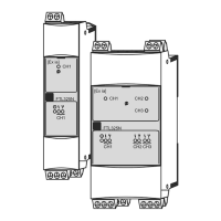
Bild 6:
Eingangsmodul pH mit
Ex-Schutzbanderole
Laschen, dienen als Griff und
zur Verriegelung des Moduls.
Straps, used as handles
and for module locking.
Figure 6:
Input module pH with
Ex protection banderole
Ex-Schutzbanderole
Ex protection banderole
abziehbare Klemmleiste
removable terminal strip

 Loading...