7/16
Endress+Hauser
Kits CM42
6. Austausch des CPU-Moduls
• Öffnen Sie den Deckel (siehe Kapitel 4).
• Die schwarzen Klemmleisten auf den Mo-
dulen sind abziehbar. Solange identische
Module getauscht werden, brauchen Sie
keine Leitungen abzuklemmen.
• Unterbrechen Sie die Geräteversorgung,
indem Sie die Klemmleiste (C) des CPU-
Moduls (B) abziehen (siehe Bild 7).
6. Exchange of the CPU module
• Open the lid (see chapter 4).
• The black terminal strips of the modules
are removeable. Therefore no need to
disconnect any cable as long as identical
modules are changed.
• Interrupt the supply of the instrument,
e.g.by unplugging the terminal strip (C)
from the CPU module (B) (see figure 7).
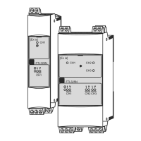
Bild 7: CPU-Modul (HART)
Figure 7: CPU module (HART)
A Flachbandkabel zum Display
Flat ribbon cable to the display
B CPU-Modul (HART-Ausführung)
CPU module (HART version)
C Klemmleiste CPU-Modul
Terminal strip CPU module
D Laschen (beidseitig an allen Modulen)
Straps (on both sides of every module)
E Eingangsmodul
Input module
• Entfernen Sie zuerst das Eingangsmodul (E):
- Ziehen Sie die Klemmleiste des Moduls ab.
- Ziehen Sie die schwarzen Laschen (D)
des Eingangsmoduls nach oben, um das
Modul zu entriegeln.
- Ziehen Sie dann das Eingangsmodul an
den beiden Laschen ganz heraus.
• Entfernen Sie nun das CPU-Modul (B):
- Entfernen sie am Module vorsichtig
das
Flachbandkabel (A) zum Display.
- Ziehen Sie die beiden schwarzen Laschen
nach oben, um das Modul zu entriegeln.
- Ziehen Sie dann das CPU-Modul an den
Laschen ganz heraus.
• Bauen Sie das neue CPU-Modul (B) ein:
- Führen Sie das neue CPU-Modul in die
Nuten an der linken Gehäusewand ein
und schieben Sie es dann bis zum An-
schlag ein. Eine Codierung in der Hut-
schiene verhindert eine falsche Position.
• First remove the input module (E):
- Unplug the terminal strip of the module.
- Pull both black straps upwards. This
releases the module fixation.
- Use the straps as handles and pull the
input module completely out.
• Now remove the CPU module (B):
- Unplug extremely cautious
the flat ribbon
cable (A) from the CPU module.
- Pull both black straps upwards. This
releases the module fixation.
- Use the straps as handles and pull the
CPU module completely out.
• Insert the new CPU module (B):
- Insert the CPU module into the notches
in the left side walll of the enclosure.
Then push the module down as far as it
will go. A coding at the mounting rail
avoids a wrong module positioning.

 Loading...