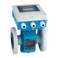
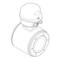
A0023061
11 Addressing using DIP switches on the I/O electronics module
1. Disable software addressing (OFF) via the top DIP switch 4 (SW).
2. Set the desired device address via the corresponding DIP switches.
Example → 11, 38: 1 + 16 + 32 = device address 49
The device demands rebooting after 10 s. After rebooting, hardware addressing is
enabled with the configured IP address.
7.3.2 Enabling the terminating resistor
PROFIBUS DP
To avoid incorrect communication transmission caused by impedance mismatch, terminate
the PROFIBUS DP cable correctly at the start and end of the bus segment.
• If the device is operated with a baud rate of 1.5 MBaud and under:
For the last transmitter on the bus, terminate via DIP switch 2 (bus termination) and DIP
switch 1 and 3 (bus polarization). Setting: ON – ON – ON → 12, 39.
• For baud rates > 1.5 MBaud:
Due to the capacitance load of the user and the line reflections generated as a result, ensure
that an external bus terminator is used.
It is generally advisable to use an external bus terminator as the entire segment can fail
if a device that is terminated internally is defective.

 Loading...


